 7 segment displays and corresponding decoders
Seven Segment Displays and Corresponding Decoders :
2. - THE DISPLAYS
2. 1. - TUBES METERS
2. 1. 1. - THE DECATRON
It was used as a counter tube in some electronic calculators.
It has a central anode surrounded by ten cathodes.
At a given moment, the discharge occurs only between a single cathode and the anode. Between the adjacent cathodes are transfer electrodes to which the pulses to be counted are applied. At each pulse, the discharge is diverted from one cathode to the next. When the discharge has made a complete revolution of the tube, a counting pulse is sent to a second similar tube which will, for example, mark the tens. Just add more tubes to record hundreds, thousands, etc ...
These tubes are abandoned, they required in fact a discharge of 200 volts and the use of transformers.
2. 1. 2. - «TROCHOTRON» DECIMAL COUNTER TUBES
The principle of the decimal counter tube is given in Figure 27.
The electron beam is emitted by a heated cathode (thermoelectronic effect).
This beam is concentrated, accelerated and deflected by means of deflection plates. It passes through the perforated anode after passing through a grid system, then hits the fluorescent screen on which are written the numbers from 0 to 9 or alphabetic characters.
They are usable up to 1 MHz maximum.
These tubes require a control circuit comprising a digital / analog conversion in order to supply the deflection electrodes.
2. 1. 3. - «NIXIE» DISPLAY TUBE OR DIGITAL INDICATOR
It comprises ten cathodes in the form of figures (or signs) superimposed. He is represented figure 28.
The display of a luminous number is obtained by applying the appropriate voltage (about 160 V) on the corresponding cathode.
Although it was launched in the 60s by BURROUGHS this technology, although old, still meets.
![]() 2. 2. - DISPLAYS HAVING SEVEN SEGMENTS AND CORRESPONDING DECODERS
2. 2. - DISPLAYS HAVING SEVEN SEGMENTS AND CORRESPONDING DECODERS
With decoders 4 to 10 and 4 to 16, it is possible to know the state of a counter by connecting for example an LED to each output and by writing next to each of them the decimal or hexadecimal number that it represent.
Figure 29 shows a decoder 4 to 10 with active outputs in state 0 with its associated LED array.
This method is however impractical because it requires the use of 10 or 16 LEDs and the numerical value of the counter status is not really displayed in clear.
This is why more complex circuits have been created that offer the possibility to directly display the corresponding signs.
These circuits are called afficheurs or English «display».
The term afficheur or «display» designates any circuit for displaying in clear a numeric or alphanumeric value. The LED is the simplest element of the displays, it allows to visualize a single bit.
There are also specialized displays such as digital watch dials. Video screens can also display information.
However, there is a type of circuit for displaying information in decimal or hexadecimal using a matrix of 7 segments consisting of 7 LEDs, so we will call these displays, 7-segment displays.
The 7-segment display can reproduce the signs 0 to 9 and A to F, it also includes a point called DP («Decimal Point» in English) which is none other than the equivalent of our decimal point.
Each segment is designated by a letter a, b, c, d, e, f, g and the point by D.P.
Figure 30 shows the arrangement of these segments.
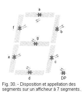
Figure 31 shows a complete 7-segment display in its case.
By properly controlling the ignition of certain segments, the desired numbers are visualized.
To visualize a zero, the segments a, b, c, d, e, f will be lit. To display a 1, the segments b, c and for a 2, the segments a, b, g, e, d for example will be lit.
Useful combinations are shown for a decimal decoder circuit in Figure 32.
The internal circuit of a 7-segment display is very simple.
Figure 33 illustrates the two existing cases.
Figure 33-a, the 8 LEDs are interconnected by their anode, this is a common anode display, while Figure 33-b, the 8 LEDs are connected by their cathode, the display is said with common cathode.
In the common cathode displays to light a segment, it is necessary to apply on the anodes corresponding to the selected sign a positive voltage so that the corresponding diodes light up.
By way of example, Figure 34 shows the pinout of a common anode display of the Monsato brand, as well as the equivalent diagram.
It is clear that one can not control a display of this type directly with the outputs of a binary counter ; indeed, it requires a special command to display the chosen decimal digit. It is therefore necessary to insert between these two circuits a decoder 4 to 7 as you can see in the block diagram of Figure 35.
We have to do to a decoder 4 to 7 for which we can draw up the truth table.
Knowing that the inputs corresponding to the segments a, b, c, d, e, f, g will for example be 0 (in the case of a common anode display) for an illuminated segment and 1 for an extinct segment, we can establish a correspondence between the binary code representative of the decimal digit chosen and the combination needed to display it.
Thus, for example to display the code 410 is 01002, it is necessary to illuminate the segments f, g, b, c.
We can say that in this case, the inputs d, e, a, are equal to 0 and the inputs f, g, b, c, are equal to 1.
The Figure 36 shows the truth table of a 7 segments BCD decoder needed to control a common anode display (active output at state 0).
We note here the outputs ON and OFF because they are outputs to open collector (ON switches on the segment, OFF off) where the use of external resistors.
There are also decoders (7448 TTL for example) whose outputs are active at 1 to control the common cathode displays.
Generally, the 4 bits of the BCD code are indicated by the letters A, B, C, D where D is the most significant bit of weight 23, while the least significant bit has a weight of 20.
This decoder has open collector outputs allowing direct connection to common anode displays. Additional entries are also planned :
![]() LT or «lamp test» which makes it possible to check the operation of the display by lighting all the segments if BI is in state 1.
LT or «lamp test» which makes it possible to check the operation of the display by lighting all the segments if BI is in state 1.
![]() BI / RBO
or «blanking
output» which allows the erasure of the segments of the display whatever the state of the other inputs.
BI / RBO
or «blanking
output» which allows the erasure of the segments of the display whatever the state of the other inputs.
![]() RBI or «ripple
blanking input» which allows the erasure of 0
on the left if A, B, C, D, are at
0.
RBI or «ripple
blanking input» which allows the erasure of 0
on the left if A, B, C, D, are at
0.
The truth table of the decoder 7447 is given in Figure 38 as well as its internal logic diagram which is a combinatorial network, and its stitching.
Figure 39 shows how one can use the ![]() entries and the
entries and the ![]() outputs to remove the insignificant 0 on a 3 digits decoding set.
outputs to remove the insignificant 0 on a 3 digits decoding set.
The ![]() of the decoder of the hundreds is at 0 permanently. Each time a 0 appears on the decoder hundreds, this 0 is cleared and the output
of the decoder of the hundreds is at 0 permanently. Each time a 0 appears on the decoder hundreds, this 0 is cleared and the output ![]() goes to 0 validating
goes to 0 validating ![]() of the next decoder.
of the next decoder.
If a 0 appears on the decoder tens, it is in turn cleared and we will validate ![]() decoder units.
decoder units.
 Click here for the next lesson or in the summary provided for this purpose. Click here for the next lesson or in the summary provided for this purpose. |
 Top of page Top of page |
|
Previous Page |
 Next Page Next Page |
Nombre de pages vues, à partir de cette date : le 27 Décembre 2019

Envoyez un courrier électronique à Administrateur Web Société pour toute question ou remarque concernant ce site Web.
Version du site : 10. 4. 12 - Site optimisation 1280 x 1024 pixels - Faculté de Nanterre - Dernière modification : 02 Septembre 2016.
Ce site Web a été Créé le, 14 Mars 1999 et ayant Rénové, en Septembre 2016.