Multiplexed Displays - LED Matrix Displays :
2. 3. - MULTIPLEX DISPLAYS
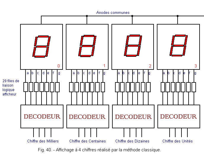
Suppose we want to display a 4 digits number. By the previous method, we will need 4 displays, 4 decoders, 28 link resistors or 29 links on all displays.
This assembly is shown in Figure 40.
To display 12 digits, which is not uncommon on a calculator, would require 85 link queues and 12 binary decode circuits - 7 segments.
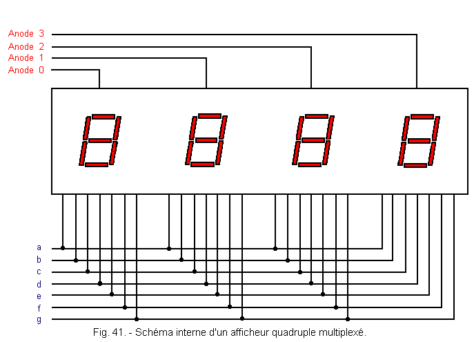
In order to simplify the wiring, there are multi-digit displays called multiplexed.
Figure 41 shows the internal diagram of a multiplexed display.
The principle of these displays is very simple :
![]() LED diodes have a very short response time and in any case shorter than that of the human eye.
LED diodes have a very short response time and in any case shorter than that of the human eye.
![]() The retinal persistence of the eye does not allow to perceive the flicker of a lamp whose recurrence period is less than 20 ms (indicative value for a duty cycle of 1).
The retinal persistence of the eye does not allow to perceive the flicker of a lamp whose recurrence period is less than 20 ms (indicative value for a duty cycle of 1).
It is therefore sufficient to send successively on the bus lines a, b, c, d, e, f, g, the codes corresponding to the figures to be displayed cyclically : unit, ten, hundred, thousand, unit, ten, hundred , thousand, unit, ... and so on.
Bus lines are : a set of conductors for simultaneously distributing information to multiple circuits.
It will of course be necessary to simultaneously select the anode of the display concerned so that the figure appears only on the decade and only the decade concerned : unity, tens, ....
The signal distribution is carried out by means of an electronic switch which we will call the multiplexer and which will be examined later, which is why it is shown schematically by a contact in Figure 42.
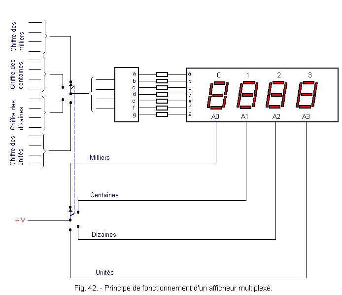
There are specialized decoders for multiplexed display circuits.
The Figure 43 shows the use of such a decoder.
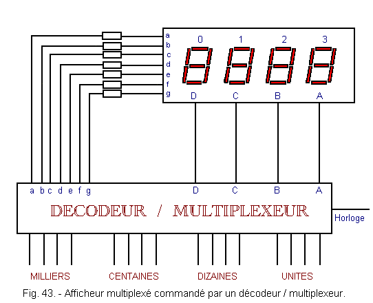
In this figure is shown a block of 4 displays and the decoder / multiplexer associated with it.
You can also find much larger blocks of displays containing decimal points and signs (plus or minus).
In this area each manufacturer presents a range of different products that can meet all needs.
![]() 2. 4. - DISPLAYS BY MATRIX LED
2. 4. - DISPLAYS BY MATRIX LED
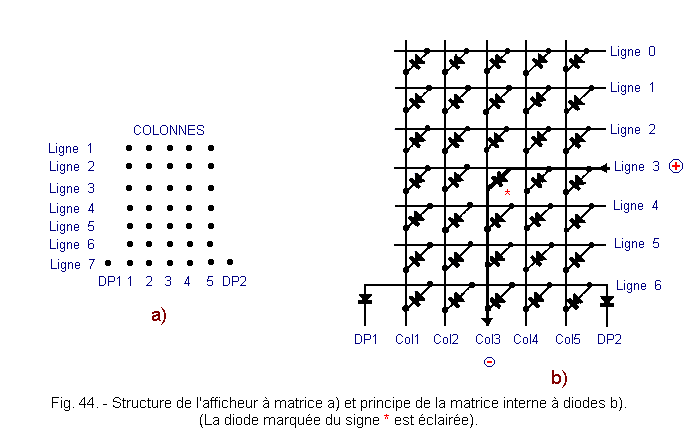
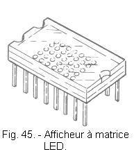
A widely used type of display uses 37 dot-shaped LEDs arranged in a 7 lines and 5 columns matrix plus 2 decimal points (DP1 and DP2), one on the right and the other on the left (Figures 44 and 45).
As for the 7 segments display by lighting the appropriate LEDs, it is possible to obtain the 10 decimal digits ; moreover, thanks to the larger number of LEDs, it is possible to represent other characters among which all the letters of the alphabet and different signs like +, -, /, (,) and still others, as represented in Figure 46.
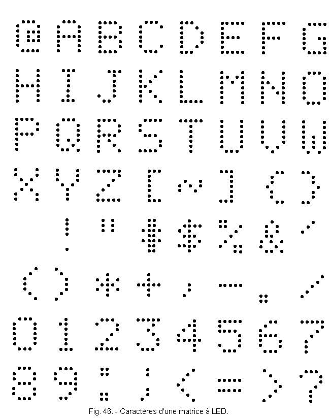
These displays require because of the larger number of LEDs of more complex decoding circuits.
Regarding the control of these circuits, it is easy to understand that given the principle of the diode matrix (Figure 44) if one wants for example to illuminate the diodes at intersections line 3 column 3 and line 4 column 4, it is necessary to light the diode located line 4 column 3.
It can therefore be deduced that it is necessary to have a circuit that performs the multiplexing of the row and column inputs so that the diodes are not switched on simultaneously but one after the other in order to eliminate this defect.
This type of circuit, also called scanning circuit, may be external or internal to the display.
The multiplexers are still unknown to us, we will say no more about this type of display.
There is also another type of dot display whose use is simpler and in which the available characters are limited to those of the hexadecimal code, in other words to the ten digits from 0 to 9 and to the letters from A to F, as you see Figure 47.
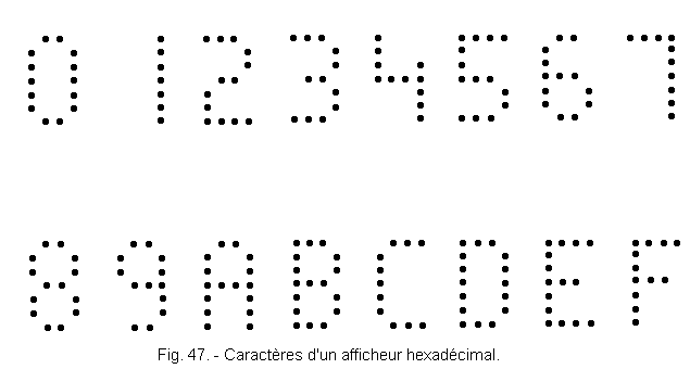
There are fewer LEDs, 20 for the characters and 2 for the decimal point, and these circuits do not require multiplexing.
In Figure 48, you can see how the LEDs and memory (Latch), decode and control circuits are arranged in the same housing as the LEDs.
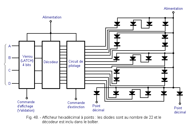
The decoder :
The most important feature of this decoder is the fact that it is included in the housing which allows to directly send the binary number provided by the counter on the display.
4 bits latch circuit :
It is used to store and display at the desired time the binary number provided.
This is very useful because often the number to be viewed is only available for a very short time insufficient to be perceived by the eye. By memorizing it in the latch, we can then visualize it during a time independent of the logic so that it is seen correctly.
Driving circuit :
This circuit makes it possible to supply the LEDs with the necessary supply current by means of a constant current generator. It has a terminal on which you can apply a signal that switches off all LEDs simultaneously. This is very useful when multi-digit numbers must be displayed with an independent display for each digit.
In case we want to display a number much lower than the maximum capacity of the display, this number will appear with one or more 0 on the left.
For example with 4 displays, the hexadecimal number that can be displayed will be FFFF. A much smaller number such 23 will appear as 0023.
The number displayed is perfectly understandable but it is desirable for aesthetic reasons to remove these 0. In this case by acting on the extinction input, they can be erased.
![]() 2. 5. - OTHER TYPES OF DISPLAY
2. 5. - OTHER TYPES OF DISPLAY
2. 5. 1. - OTHER LED DISPLAYS
There are also other types of 9, 14 or 16 segments LED displays (Figure 49-a).
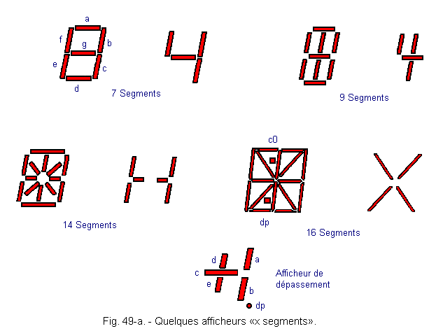
Each time, it will be sufficient to have the appropriate decoder.
The most advanced (16 segments) allows all alphanumeric representations.
There are so-called overlay displays (sometimes called half digits).
These displays have only 5 segments, and are used to indicate the sign + or -, as well as the number 1.
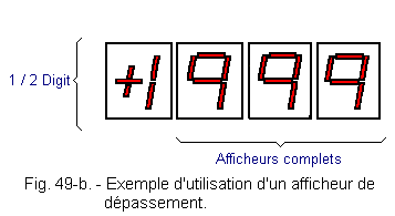
In a digital display voltmeter, for example, the first (leftmost) display will be 1 / 2 Digit.
Figure 49-b shows a display of 3 Digits 1 / 2.
LCD displays or L.C.D. (Liquid Crystal Display) include segments such as LED displays. a - Physics of liquid crystals Some bodies, although liquid, have a structure close to that of solid crystals. They are characterized by a specific alignment of their molecules. There are three types of structures : The molecules are divided into layers that regularly stack on top of each other. There is currently no industrial interest (Figure 50-a). In each plane, the molecules are parallel. When one passes successively from one plane to another, the axis of the molecules turns at a constant angle. Therefore, this structure is called : helical structure (Figure 50-b). The major axes of the molecules are parallel to a certain direction but their centers of gravity are randomly distributed as in an ordinary liquid. Molecules can move in all directions in all three dimensions (Figure 50-c).
![]() 2. 5. 2. - LIQUID CRYSTAL DISPLAYS
2. 5. 2. - LIQUID CRYSTAL DISPLAYS![]() The smectic state :
The smectic state :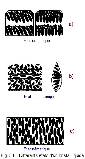
![]() The cholesteric state :
The cholesteric state :![]() The nematic state :
The nematic state :
 Click here for the next lesson or in the summary provided for this purpose.
Top of page
 Previous Page
 Next Page
Nombre de pages vues, à partir de cette date : le 27 Décembre 2019
Envoyez un courrier électronique à Administrateur Web Société pour toute question ou remarque concernant ce site Web.
Version du site : 10. 4. 12 - Site optimisation 1280 x 1024 pixels - Faculté de Nanterre - Dernière modification : 02 Septembre 2016.
Ce site Web a été Créé le, 14 Mars 1999 et ayant Rénové, en Septembre 2016.
 LED Matrix Displays