 Incandescent Filament Displays Incandescent Filament Displays |
 Fluorescent tubes Fluorescent tubes
|
 Cathodic tubes Cathodic tubes |
 Comparisons between different displays Comparisons between different displays
|
 Footer Footer |
Incandescent Filament Displays ... :
b - Constitution of L.C.D. displays
The liquid crystal displays consist of a layer of liquid crystal between two glass plates coated with conductive materials.
The alignment of the crystal molecules can be changed by applying a voltage across its two plates.
This alignment change makes it possible to visualize segments comparable to those of an LED display except that they emit no light.
The electrical contact with the liquid crystal is achieved by means of a transparent conductor. Since the appearance of the sign depends on the alignment of the molecules, the direction in which light hits the crystal is critical. For this reason, light polarizing filters are used which are attached to the front and back of the display to control the display.
c - Operating principle of L.C.D. displays
It is based on the principle of «reflection» or «non-reflection» of light through polarizing filters.
Light is an electromagnetic wave of between 400 and 750 nanometers in length. In the most common case, the oscillations of the electric fields are melted in any direction. We call «natural» light.
There is a light called «coherent» or «polarized» whose oscillations of the electric field are made in a very precise direction (case of the laser), (Figure 51-a).

(The oscillations of the electric field are in a precise direction).
«Polarized» (or coherent) light is obtained by scattering wild light in an opaline medium or «polarizing filter». These filters consist of crystals oriented in a well defined direction (Figure 51-b).
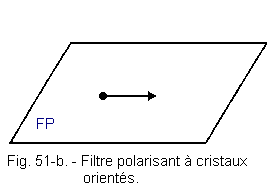
It is important to note that these filters are transparent and not opaque.
Experience of the two polarizing filters :
Suppose a light source, from a bulb, or obtained by reflection with a polished surface.
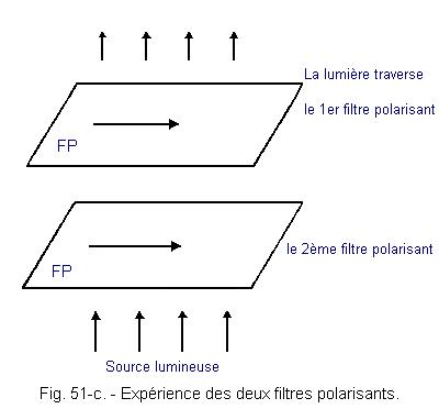
By placing on this light source two filters oriented in the same direction, it is found that the light passes through them, without significant absorption, as shown in Figure 51-c.
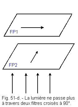
By gradually crossing one of the two filters, it is found that the light passes more and more badly until total absorption (cross filters at 90° as shown in Figure 51-d).
Now let us introduce a thin, transparent crystal between the two filters (Plexi sheet for example), the light crosses the two filters again. This is due to the rotating power of the crystal, which causes the light to start in a specific direction and cancels the crossover effect of the polarized filters.
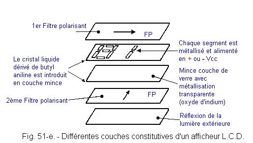
The liquid crystal, introduced in a thin layer between the two crossed filters, will restore, like the plexi, the passage of the light.
An electric field traversing locally this set, will disorient crystals of the liquid crystal, and again, the light will not pass (Figure 51-e).
d - Different types of displays L.C.D.
There are two types of LCD displays :
![]() Dynamic broadcasting systems :
Dynamic broadcasting systems :
They use a pure nematic crystal to which is applied an electric field accompanied by current flow.
In the absence of applied voltage, the liquid crystal is perfectly transparent. When a voltage is applied, the crystal becomes highly diffusing because the molecules are oriented in all directions.
![]() Field effect systems :
Field effect systems :
When a nematic liquid crystal is subjected to an electric field, it follows a variation in the direction of the alignment of the molecules (helical rotation of the molecules) without causing a dynamic diffusion phenomenon. An alternating voltage of frequency higher than the relaxation frequency of the liquid crystal is adopted, but too weak to cause the oscillation of the molecules, is about 5 kHz.
In field effect systems, the helical nematic effect is used to vary the rotation of the polarized light continuously from 0 to 90°.
This causes an optical delay that breaks down the white light. Red, yellow and green are thus obtained, unlike dynamic scattering systems which are themselves achromatic (no clean colors).
The nematic used is a butylaniline derivative, the transparent electrodes are in tin oxide or indium oxide.
These systems are very low consumption and their high contrast allows them to be used in watches.
e - Display control circuits L.C.D.
For reasons previously seen but also to avoid electrolysis deposition that could damage the displays they are controlled by an AC signal having no DC component.
For so-called field effect displays, a control voltage of 2 to 10 V and a few kilohertz of frequency are used.
For dynamic scattering displays, a control voltage of 7 to 30 V and 20 to 400 Hz is used.
The LCD displays are controlled by special decoders providing the appropriate square voltages.
Figure 52 shows the connection of a decoder / driver with a display L.C.D. field effect.
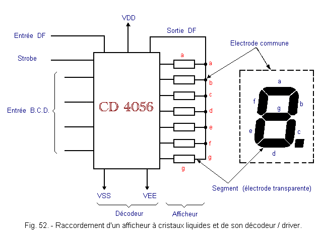
Figure 53 shows the internal structure of a decoder / driver for display L.C.D.
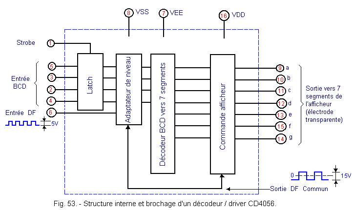
The decoder is powered between VSS and VDD is 5 to 15 volts.
The display is supplied between VDD and VEE, which allows thanks to the level adapter circuit to have on the decoder output a level of amplitude 15 V even if the level available on the inputs B.C.D. is only 3 V for example.
The valid Strobe entry at 1 transfers the code B.C.D. present at the input of the integrated circuit at the input of the level adapter.
The DF (Display Frequency) input is powered by a 5 V square wave signal of amplitude and frequency between 30 Hz and 200 Hz.
When a BCD code is present at the input of the level adapter for DF = 0, the output of the corresponding segment is high.
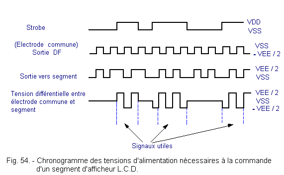
If a square signal is present at the input DF, the corresponding output of the selected segment is fed by a signal phase-shifted by 180° with respect to DF. The outputs of the unselected segments are fed by a square signal in phase with DF, so that only the selected segments show a potential difference across their terminals (voltage between output of the display control for the selected segment and DF).
The timing diagram of Figure 54 shows the different signals as described.
f - Advantage of LCD displays and disadvantages :
![]() Their consumption is almost zero hence their widespread use in quartz watches (consumption : about 15 nano-amperes per square millimeter).
Their consumption is almost zero hence their widespread use in quartz watches (consumption : about 15 nano-amperes per square millimeter).
![]() Their contrast increases with illumination.
Their contrast increases with illumination.
![]() They do not produce light by themselves and therefore require good lighting.
They do not produce light by themselves and therefore require good lighting.
![]() Their response time is high : 100 to 300 milliseconds.
Their response time is high : 100 to 300 milliseconds.
![]() Their price is high.
Their price is high.
![]() Because they require an alternating signal, multiplexing is difficult.
Because they require an alternating signal, multiplexing is difficult.
![]() 2. 5. 3. - DISPLAYS WITH INCANDESCENT
FILAMENTS
2. 5. 3. - DISPLAYS WITH INCANDESCENT
FILAMENTS
In this technology, each segment is in fact a filament identical to that of an incandescent lamp.
The advantage of these displays is their high brightness and the possibility with a filter to get any color.
Their main disadvantage is their consumption.
Figure 55 shows the pin assignment and internal organization of a minitron filament display as well as an example of a connection (the decoder 7447 being represented only by its block diagram).
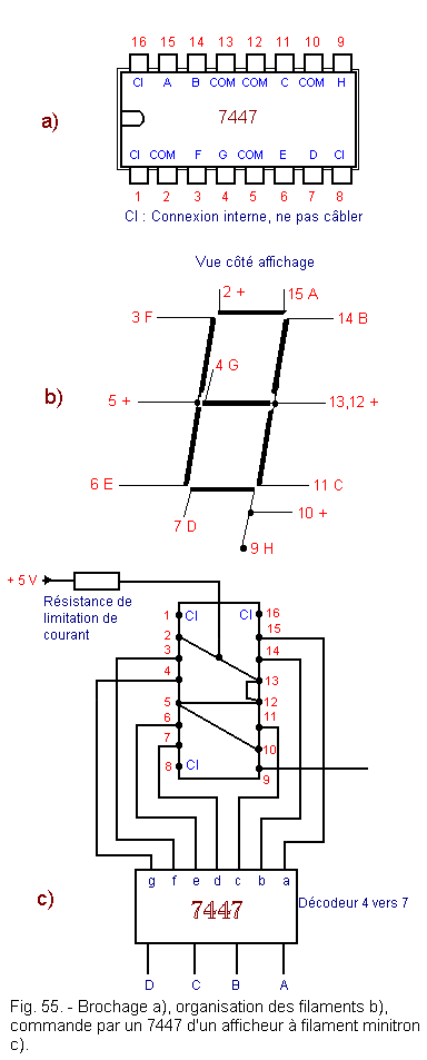
The decoder 7447 allows the direct control of filament displays because its outputs can receive up to 40 mA (see Figure 37).
Figure 55-c shows the connections to be made to control the circuit.
We can see that all the filaments are controlled between 0 and 5 V. All 5 V (pins 2, 5, 10, 12, 13) are connected together. The free end of the filament is then controlled by the corresponding low output of the decoder thereby passing a current through the filament.
It is recommended for this type of displays to feed the filaments through a load-independent constant current power source to provide uniform brightness across all segments of all displays.
![]() 2. 5. 4. - FLUORESCENT TUBES
2. 5. 4. - FLUORESCENT TUBES
The technology used is reminiscent of vacuum tubes.
A filament heated just below the incandescence serves as a cathode and thus ensures the emission of electrons.
Metal segments arranged like those of the 7 segments displays act as anodes.
When an anode is selected, the electrons emitted by the cathode-filament «bombard» the selected segments. The tube containing a gas derived from phosphorus, it follows a blue light emission near the selected segments.
This technique allows the realization of panels of 8 to 16 digits.
Given its low cost, the Japanese use this technology in office calculators.
![]() 2. 5. 5. - THE CATHODIC TUBES
2. 5. 5. - THE CATHODIC TUBES
Their principle is that of the vacuum tube.
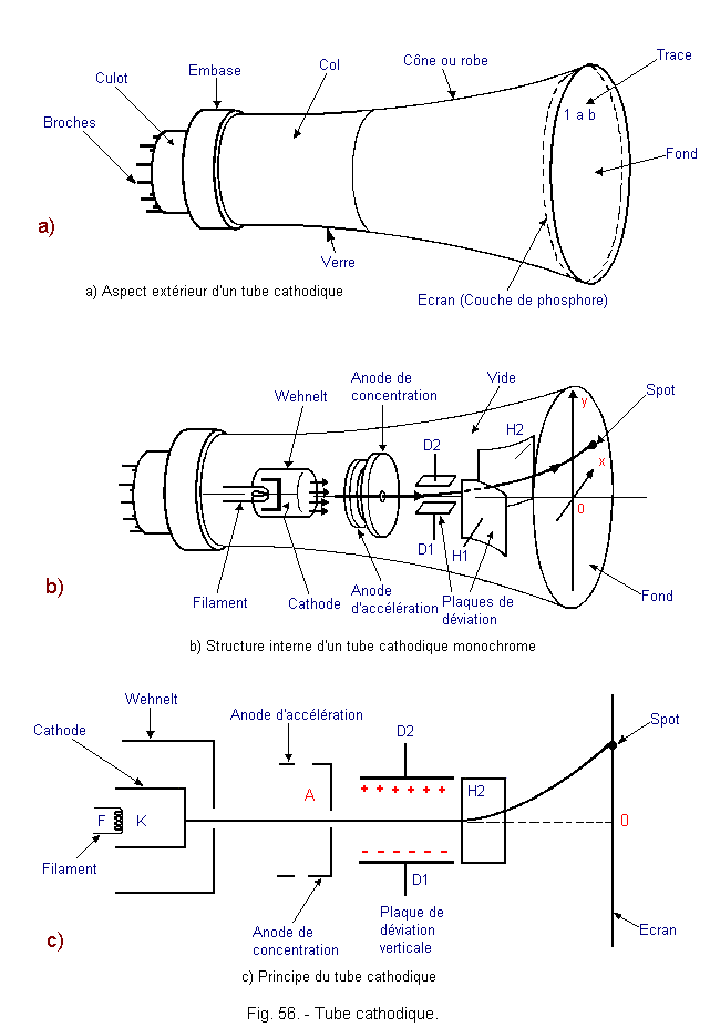
The electrons emitted by a cathode heated by a heating filament F are concentrated by a special grid called Wehnelt or control, accelerated by anode A and concentrated in a fine brush then deflected by deflector plates or (deflector) horizontal and vertical then projected on the screen constituted by the bottom of the tube covered with phosphorus. The electronic «bombardment» of the screen then produces a light or spot whose shape can be varied.
A cathode ray tube is shown in Figure 56-a. Its internal constitution is represented in Figure 56-b. Its operating principle is illustrated in Figure 56-c.
Some Cathodic tubes have three barrels to excite phosphors giving a red light, green or blue to restore the color. These tubes are called «trichromatic» as opposed to other so-called «monochrome» tubes.
Cathode ray tubes require high voltages (several thousand volts).
The cathode ray tubes allow a considerable flexibility of use. Indeed, they allow to represent alphanumeric or alphabetic characters, decimal digits, special symbols, graphs ...
They equip a multitude of computer terminals.
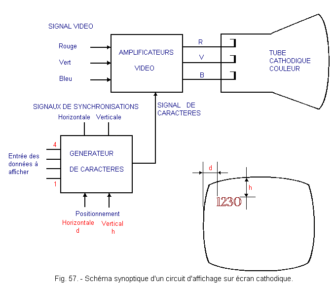
However, it is necessary to have a character generator to modulate the electron brush emitted by the cathode to obtain the desired sign.
Figure 57 gives the block diagram of the set.
![]() 2. 5. 6. - COMPARISONS BETWEEN THE DIFFERENT DISPLAYS
2. 5. 6. - COMPARISONS BETWEEN THE DIFFERENT DISPLAYS
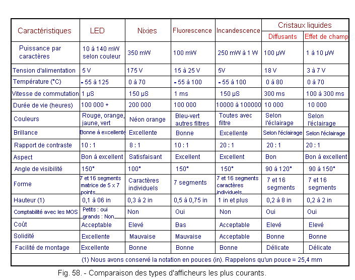
You can see on the table in Figure 58 all possible comparisons between the different types of displays.
It should be noted, however, the very low consumption of liquid crystal displays.
You can also notice the very long reaction time of these displays.
2. 5. 7. - CONCLUSION
In this theory, we have seen a large number of display circuits and decoder circuits.
We have seen a large number of codes, other codes still exist such as U.S.A.S.C.I.I. which will be treated later when we look at microprocessors.
In the next theory, you will discover adders, comparators as well as multiplexers / demultiplexers.
 Click here for the next lesson or in the summary provided for this purpose. Click here for the next lesson or in the summary provided for this purpose. |
|
 Previous Page Previous Page |
 Next Page Next Page |
Nombre de pages vues, à partir de cette date : le 27 Décembre 2019
Envoyez un courrier électronique à Administrateur Web Société pour toute question ou remarque concernant ce site Web.
Version du site : 10. 4. 12 - Site optimisation 1280 x 1024 pixels - Faculté de Nanterre - Dernière modification : 02 Septembre 2016.
Ce site Web a été Créé le, 14 Mars 1999 et ayant Rénové, en Septembre 2016.
