 Decade decoder Decade decoder |
 Decoding a Johnson Counter Decoding a Johnson Counter |
 Footer Footer |
Cascading of Decimal Counters :
1. 9. - CASCADING DECIMAL COUNTERS
Referring to Figure 18, the diagram of the modulo 10 counter outputs discussed in the previous theory.
.gif)
If we associate the number 1 with the high level and the number 0 with the low level as usual, we obtain the table of the Figure 19 where we can notice that from 0 to 9 the circuit counts in binary code.
Fig. 19. - The counter outputs are in binary code.
| Counter states | Q4 | Q3 | Q2 | Q1 |
| 0 | 0 | 0 | 0 | 0 |
| 1 | 0 | 0 | 0 | 1 |
| 2 | 0 | 0 | 1 | 0 |
| 3 | 0 | 0 | 1 | 1 |
| 4 | 0 | 1 | 0 | 0 |
| 5 | 0 | 1 | 0 | 1 |
| 6 | 0 | 1 | 1 | 0 |
| 7 | 0 | 1 | 1 | 1 |
| 8 | 1 | 0 | 0 | 0 |
| 9 | 1 | 0 | 0 | 1 |
As you saw in Theory 9, it is possible to cascade several meters by connecting the CARRY output of the first one to the Chip ENABLE T (C.E.T.) input of the second and so on.
Three synchronous modulo 10 counters thus connected form the circuit shown in Figure 20.
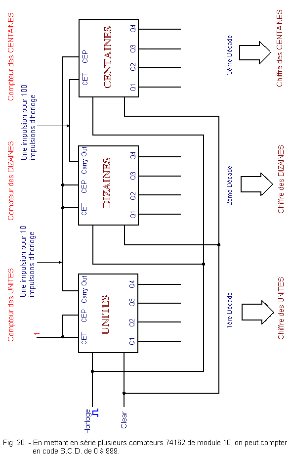
Each decade, when it returns to 0, increments the next decade of 1. Thus the first decade will count each pulse, the second will count one every ten and the third one every hundred.
The levels of the four outputs (Q1, Q2, Q3 and Q4) of each decade form a binary code arranged according to the table of Figure 19.
We can find the decimal number, result of the counting, knowing that the four outputs of the first counter indicate the number of units, the four outputs of the second one of the tens and those of the third that of the hundreds.
In this way, the counter uses the code B.C.D.
![]() 1. 10. - DECODER OF DECADE
1. 10. - DECODER OF DECADE
As for the modulo 16 counter, the decade often needs a decoder for its outputs. In commerce, there are decoders with 4 inputs and 10 outputs that fulfill precisely this task (Figure 21).
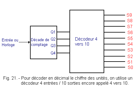
These decoders have 4 inputs and 10 outputs. They allow when one displays a binary number on the 4 entries to obtain the decimal equivalent by validating one of the ten outputs. They therefore only accept as input binary numbers between 0000 and 1001 (that is, between 010 and 910).
These decoders are called 4 to 10, so the decoders with hexadecimal outputs are called 4 to 16.
Figure 22 a-b shows a MOS decoder, type 4028 B - 4 / 10 whose outputs are active in state 1. (Other decoders have active outputs in state 0).
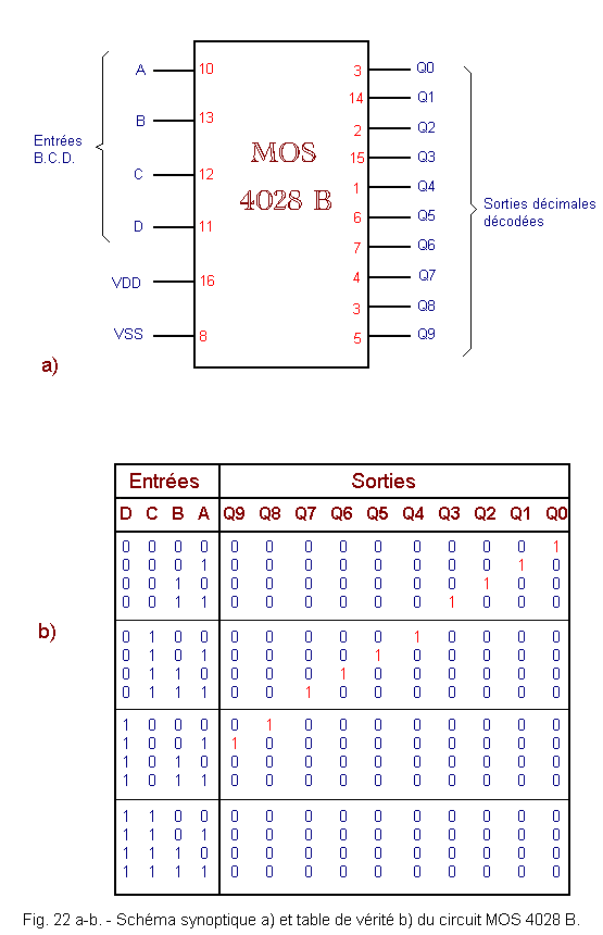
Figure 22 c-d shows the association of two 4028 B decoders in order to produce a 4 / 16 decoder.
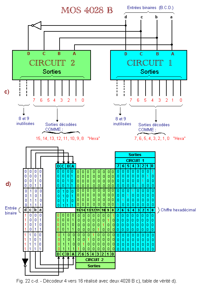
The truth table indicates the status of the outputs for each combination «d, c, b, a» input.
The outputs can be used to decode different codes. Here, we use two cascaded decoders in which only outputs from 0 to 7 are used.
Up to 716, the input «d» being 0, the circuit 1 has its outputs enabled and the circuit 2 (the bit «d» being inverted) can not have used outputs validated.
From 810, the bit «d» being 0, the circuit 2 has its outputs 0 to 7 which can be enabled according to the combinations of «a, b, c» while the used outputs of the circuit 1 can not be validated. Outputs 0 to 7 of the second circuit are interpreted as 8, 9, 10, 11, 12, 13, 14, 15.
So we have a hexadecimal decoder.
![]() 1. 11. - DECODING A JOHNSON COUNTER
1. 11. - DECODING A JOHNSON COUNTER
As you saw in the previous theory, the Johnson counter counts in a very special way.
Indeed, in this counter consisting of five flip-flops, the outputs can take ten different combinations of 2 outputs each as shown in green Figure 23.
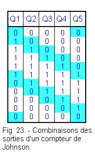
The Johnson code is not a weighted code.
Each of the 10 combinations is assigned a decimal code of 0 to 9 as described in Figure 24.
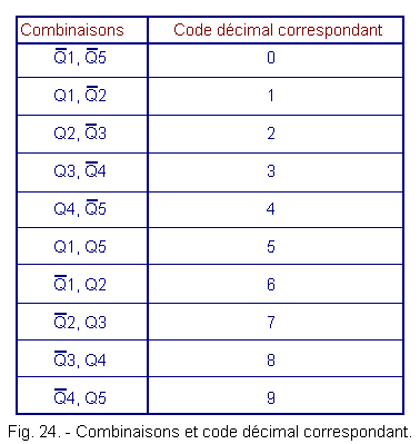
It is therefore necessary to decode the state of the outputs to individualize each combination so as to have 10 outputs.
A good number of solutions are then available and we will retain that adopted in the integrated circuit 4017 B.
This integrated circuit combines in a single housing a Johnson meter with 5 stages and the appropriate decoder.
The block diagram of this circuit is shown in Figure 25 as well as its pinout.
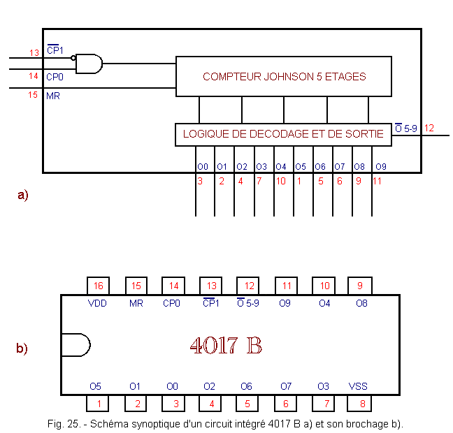
The input CP0 makes it possible to trigger the counter on a rising edge while the entry
![]() 1
makes it possible to trigger the counter on a falling edge. The MR entry allows the reset to 0 general. It is active at level H (high).
1
makes it possible to trigger the counter on a falling edge. The MR entry allows the reset to 0 general. It is active at level H (high).
Outputs O0 to O9 are the decoded outputs. The output ![]() 5
- 9 allows the cascading of the counters : it is sufficient to connect it to the input CP0 of the following counter. It is an active report at level L (low).
5
- 9 allows the cascading of the counters : it is sufficient to connect it to the input CP0 of the following counter. It is an active report at level L (low).
Figure 26-b shows the internal scheme of the 4017 B decoder counter.
It includes a Johnson counter with five flip-flops followed by a combinatorial decoding network. The timing diagram (Figure 26-a) shows the successive validation of the decoded outputs as the clock pulses arrive.
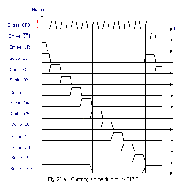
In the integrated circuit 4017 B, the different combinations are obtained using NOR circuits each followed by a buffer (YES circuit used as an amplifier).
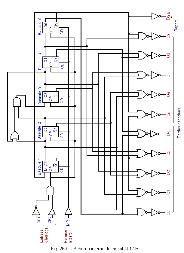
For example, the validation of the output Q4 is shown in bold in Figure 26-b. This output, corresponding to the decimal code 4, goes to a logic level H for the combination of the outputs ![]() 4
and Q5 of the counter.
4
and Q5 of the counter.
 Click here for the next lesson or in the summary provided for this purpose. Click here for the next lesson or in the summary provided for this purpose. |
|
 Previous Page Previous Page |
 Next Page Next Page |
Nombre de pages vues, à partir de cette date : le 27 Décembre 2019
Envoyez un courrier électronique à Administrateur Web Société pour toute question ou remarque concernant ce site Web.
Version du site : 10. 4. 12 - Site optimisation 1280 x 1024 pixels - Faculté de Nanterre - Dernière modification : 02 Septembre 2016.
Ce site Web a été Créé le, 14 Mars 1999 et ayant Rénové, en Septembre 2016.
