 Decoder for Counters Decoder for Counters |
 Hexadecimal code Hexadecimal code |
 Other 4-bit codes Other 4-bit codes |
 B.C.D codes B.C.D codes |
 Aiken Code Aiken Code |
 Code + 3 Code + 3 |
 Code Gray Code Gray |
 Footer Footer
|
The Four bit Counter - Decoders for Counters :
1. 5. - THE FOUR BIT COUNTER
Let us take again the examination of the synchronous counter of module 16 seen in the preceding theory.
The circuit and the voltage levels on the four outputs are shown in Figure 9.
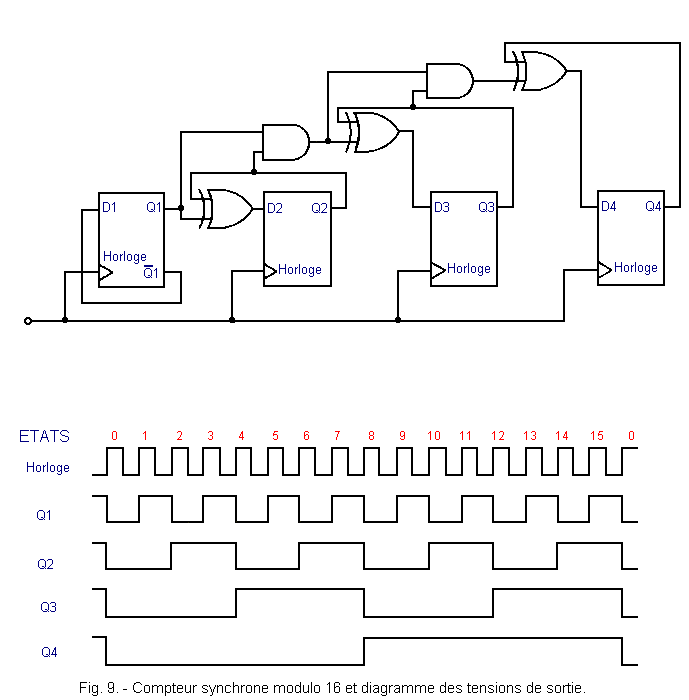
The circuit has 16 states, it goes from one to the other at each clock pulse. The states are distinguished from each other by observing the voltage level present on each output.
For example, state 3 is distinguished by high voltage levels on outputs Q1 and Q2 and low levels on outputs Q3 and Q4.
Now let's take a closer look at how the different outputs vary for each state.
As you can see, the output Q1 changes level every clock pulse and more precisely on its rising edge ; Q2 changes on the other hand every two pulses, Q3 every four and Q4 every eight pulses.
The number of clock pulses needed to change a flip-flop state is 1 for Q1, 2 for Q2, 4 for Q3, 8 for Q4, as summarized in the table in Figure 1
| Output | Weight |
| Q1 | 1 |
| Q2 | 2 |
| Q3 | 4 |
| Q4 | 8 |
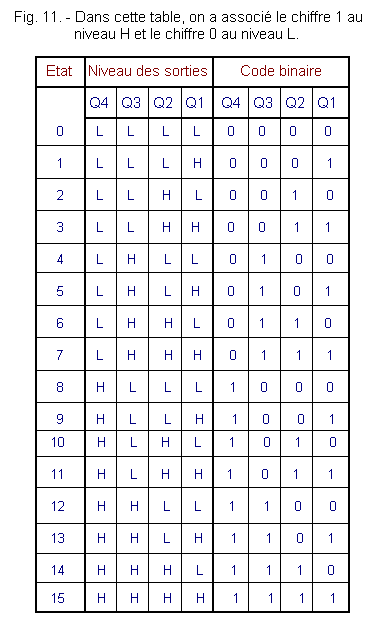
Each output can be assigned the binary digit 1 if it is at the level H and the binary digit 0 when it is at the level L as represented in Figure 11.
Comparing this table with that of Figure 7, we see that in the last column of the two tables we find a number in binary code.
In addition, the weight of each digit corresponds to the weight of each output.
The counter therefore uses the binary code. Its outputs give a binary number which, translated into decimal code, directly indicates the state reached by the counter and therefore the number of clock pulses that have reached that moment.
In practice, the number of each state corresponds to the number of clock pulses necessary to arrive at this state starting from the state 0.
You can see that the output farthest from the input, that is to say Q4 is the one with the greatest weight, it corresponds to the largest bit of the binary number whose weight is 8. This bit is called «most significant bit» (Figure 12) abbreviated MSB (initials of the English words «Most Significant Bit», that is, «bit le plus significatif»).
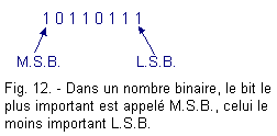
The output Q1 corresponds to the least important bit : its weight is 1, it is called «bit le moins significatif» in short L.S.B. (initials of the English words Least Significant Bit).
![]() 1. 6. - DECODER
FOR METERS
1. 6. - DECODER
FOR METERS
We have seen that most counters count in binary code.
It is however useful, and even necessary, to decode the outputs by sending the corresponding signals to appropriate circuits which, without altering the transmitted information, transform the basic code into another, more convenient operation.
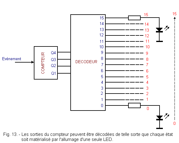
It is possible, for example, with a suitable decoder circuit, to obtain directly, instead of the usual four bits, 16 informations, 1 or 0, available on 16 different outputs and thus to control the lighting of LEDs representing the decimal codes 0 to 15.
In Figure 13, you can see the block diagram of the decimal bit-decoder system.
From the circuit point of view, a decoder of this type is not very complex. Each output of the counter corresponds to a network of doors and inverters chosen appropriately. For example for the number 7, we will have the network of Figure 14.
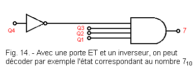
As you can see the level at the output of the AND is H only when Q1, Q2, Q3 are at the H level and Q4 at the L level. This occurs for the combination 01112 which in binary corresponds to 710.
Sometimes it is not necessary for all 16 outputs to be present. It is then enough to decode the state which only interests us. When, for example, a number of events have been counted (parts on a treadmill, people in a room, etc.), it may be necessary to signal it and to perform an action, for example (stop the treadmill or trigger ventilation).
In this case, only one circuit prepared to decode the chosen number is necessary.
![]() 1. 7. - HEXADECIMAL CODE
1. 7. - HEXADECIMAL CODE
It is quite common to encounter digital circuits using four bits.
The counter examined in the previous paragraph operates on four bits. The registers, comparators and other components operate on 4, 8, 16 bits or other multiples of 4.
Inside the computers too, the information is put in the form of a group of a succession of bits.
Currently, most broadcast microprocessors operate on 8 bits. But other microprocessors also use 16 or 32 bits. Large computers work with 32 bits for I.B.M. and 48 bits for Control Data.
But in all cases, we find successions of bits at 1 or 0 with numbers of 4 or 48.
In order to simplify these writings which would be tedious by means of the binary code, one uses the hexadecimal code or base code 16.
With this code, we can replace a group of 4 bits by a single character.
In the previous counter, 4 bits could represent 16 distinct states, that is, we could count from 00002 to 11112.
The hexadecimal system uses 16 signs : the first ten well-known signs 0, 1, 2, 3, 4, 5, 6, 7, 8, 9 to which we added A for 10, B for 11, C for 12, D for 13, E for 14, F for 15. You can find this in the table in Figure 15.
| Number | Decimal code | Binary code | Hexadecimal code |
| Zero | 0 | 0000 | 0 |
| One | 1 | 0001 | 1 |
| Two | 2 | 0010 | 2 |
| Three | 3 | 0011 | 3 |
| Four | 4 | 0100 | 4 |
| Five | 5 | 0101 | 5 |
| Six | 6 | 0110 | 6 |
| Seven | 7 | 0111 | 7 |
| Eight | 8 | 1000 | 8 |
| New | 9 | 1001 | 9 |
| Ten | 10 | 1010 | A |
| Our | 11 | 1011 | B |
| Twelve | 12 | 1100 | C |
| Thirteen | 13 | 1101 | D |
| Fourteen | 14 | 1110 | E |
| Fifteen | 15 | 1111 | F |
Contrary to what one can think, the hexadecimal code does not represent a complication, but on the contrary a simplification because it makes it possible to transcribe in a more brief way the binary numbers generally quite long.
Indeed, it is possible to go from binary code to hexadecimal with great ease.
Take for example the binary number 11010011 and turn it into a hexadecimal number.
The transformation can be achieved by grouping the four to four right-to-left bits and replacing each group with the corresponding hexadecimal number that is in the last column to the right of Figure 15 as shown below :

The hexadecimal number thus obtained can be broken down as follows :
(D x 161) + (3 x 160) = (1310 x 1610) + (310 x 110) = 20810 + 310 = 21110
The inverse transformation is just as simple : it suffices to transform each hexadecimal digit into a corresponding four-bit group as in the following example :

![]() 1. 8. - OTHER
4-BIT CODES
1. 8. - OTHER
4-BIT CODES
The binary numeration which, as we have seen, is perfectly adapted to the use in a digital electronic system, is however not very manageable for the man, because he is accustomed to the decimal numeration.
This difficulty is particularly felt when loading or reading the data supplied to a digital control system or a computer.
In fact, the data expressed with the pure binary system are not instantly understandable (by the man), the transition between the binary system and the decimal system being quite complicated.
To overcome these disadvantages, binary coding systems of decimal numbers have been developed.
In these codes, at each decimal digit, a combination of binary digits is mapped.
To express the first ten Arabic characters with binary numbers, at least four digits are required. With these four binary digits, we can have the following sixteen combinations :
| 0000 | 0100 | 1000 | 1100 |
| 0001 | 0101 | 1001 | 1101 |
| 0010 | 0110 | 1010 | 1110 |
| 0011 | 0111 | 1011 | 1111 |
Since the available binary combinations are larger than the decimal characters, it is possible to choose several systems for the representation of the decimal digits. These various systems are called codes and are represented in Figure 16.
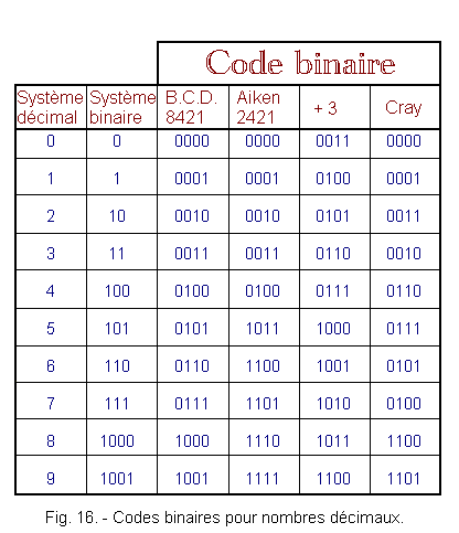
There are two types of codes : the codes «weighted» and «unweighted» codes.
In general, codes are «weighted» when there are numbers that indicate the «weight» of the binary digits of the corresponding groups.
By multiplying these numbers by the corresponding binary digits, we obtain the decimal equivalence.
All other codes in which we can not identify the weight of the binary digits of the corresponding groups are called «unweighted» and are developed on a complex mathematical development basis or more simply are characterized by specially made tables.
Different codes have been devised, having various logical and arithmetic properties. The choice of one or the other type of code depends exclusively on the applications for which it is intended.
In the table of Figure 16, are reported some of the most common codes.
![]() 1. 8. 1. - CODES
B - C - D
1. 8. 1. - CODES
B - C - D
A widely used type of code is the binary coded decimal code generally called «B.C.D.» for «Binary Coded Decimal».
Usually, the binary code is better suited for digital circuits, but it is difficult to translate a binary number into decimal especially when you have a large number of bits.
The code B.C.D., used in association with appropriate decoders, allows on the other hand to easily translate, in binary expression the decimal numbers and vice versa.
The code B.C.D. consists of the following : each digit of the decimal number is encoded into a pure binary number of four bits.
Figure 17-a shows the coding B.C.D. decimal numbers from
Fig. 17-a. - Numbers 11010 to 12510 coded in B.C.D.
| Decimal code | Code BCD | Code BCD | Code BCD |
| 110 | 0001 | 0001 | 0000 |
| 111 | 0001 | 0001 | 0001 |
| 112 | 0001 | 0001 | 0010 |
| 113 | 0001 | 0001 | 0011 |
| 114 | 0001 | 0001 | 0100 |
| 115 | 0001 | 0001 | 0101 |
| 116 | 0001 | 0001 | 0110 |
| 117 | 0001 | 0001 | 0111 |
| 118 | 0001 | 0001 | 1000 |
| 119 | 0001 | 0001 | 1001 |
| 120 | 0001 | 0010 | 0000 |
| 121 | 0001 | 0010 | 0001 |
| 122 | 0001 | 0010 | 0010 |
| 123 | 0001 | 0010 | 0011 |
| 124 | 0001 | 0010 | 0100 |
| 125 | 0001 | 0010 | 0101 |
As you can see, the code B.C.D. is a synthesis of the decimal code and the binary code.
Within each group of 4 bits, the binary code remains valid and we find the weights 1, 2, 4, 8. On the other hand, for the weight of the groups with respect to each other, the weighting is that of the decimal system as the example of Figure 17-b.
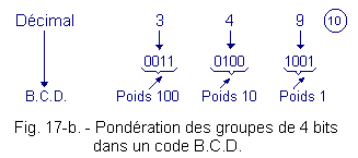
The advantage offered by the coding method B.C.D. is to allow the use of digital circuits that work in binary code while keeping a decimal weight for each digit expressed in binary.
For this reason, all pocket calculators use the code B.C.D.
However, there is a disadvantage to this coding system, indeed, it requires a higher number of bits than that required in binary code.
For example
402210
will be written :
-
in binary : 1111 1011 01102, that is 12 signs.
-
in B.C.D. : 0100 0000 0010 0010BCD, that is 16 signs.
In most cases, it becomes too expensive to use this code, because each additional bit requires additional components.
![]() 1. 8. 2. - AIKEN CODE
1. 8. 2. - AIKEN CODE
It's a 2421 «weighted» code. For the decimal digits 0, 1, 2, 3, 4, it agrees with the B.C.D. code, while for the decimal numbers 5, 6, 7, 8, 9, it matches the numbers 11, 12, 13, 14, 15 of the pure binary code.
This code has the property of being self-complementary, which makes it possible to obtain the complement to 9 of the codified numbers, by simply replacing the 0 by 1 and the 1 by 0.
Take, for example, the decimal digit 2 coded 0010, by inverting the binary number 0010, we obtain 1101 group corresponding to the digit 7 which is the complement to 9 of 2. This property is useful in the calculation of the subtraction.
For example, the number 63 in Aiken code is written this way : 1100 0011.
![]() 1. 8. 3. - CODE
+ 3
1. 8. 3. - CODE
+ 3
This code is also called Stibiz by the name of its inventor and it is an «unweighted» code.
It uses the four-digit combinations of the pure binary between the decimal numbers 3 and 12.
Each number is obtained by adding 3 to each digit of the decimal number and coding it in B.C.D.
In this system, the combinations 0000 and 1111 do not appear. For example, the number 63 in code + 3 is written 1001 0110.
![]() 1. 8. 4. - GRAY CODE
1. 8. 4. - GRAY CODE
This code, also unweighted, the property to present in the transition from one number to the next, the variation of a single «bit», that is to say, a single digit of the binary group. It presents a lower risk of hazards in sequential.
In this code, the decimal number 63 is written 0101 0010. In addition to the described codes, there are others with various properties but which will not be examined because they are out of the scope of the lessons present in all the courses.
 Click here for the next lesson or in the summary provided for this purpose. Click here for the next lesson or in the summary provided for this purpose. |
|
 Previous Page Previous Page |
 Next Page Next Page |
Nombre de pages vues, à partir de cette date : le 27 Décembre 2019
Envoyez un courrier électronique à Administrateur Web Société pour toute question ou remarque concernant ce site Web.
Version du site : 10. 4. 12 - Site optimisation 1280 x 1024 pixels - Faculté de Nanterre - Dernière modification : 02 Septembre 2016.
Ce site Web a été Créé le, 14 Mars 1999 et ayant Rénové, en Septembre 2016.
