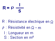
W-m.
.gif)
To supplement our example, the figure 1-c gives the resistance of 100 m length
drivers and 1 mm2 of section but made out of various materials, and this with an aim of carrying out a better comparative
analysis of these metals at the point of the electric sight.
Appear 1-c - comparative Analysis.
| Metal |
Resistance
of a 100 m length wire and 1 mm2 of section |
| Money |
1,6
W |
| Copper |
1,7 W |
| Aluminum |
2,8
W |
| Tungsten |
5,6
W |
| Iron |
9,6
W |
| Platinize |
10 W |
| Lead |
22 W |
| Mercury |
95 W |
Lastly, to close this chapter on electric resistance, it should be known that this one varies with the
temperature because the resistivity of the substance also varies with the temperature. However, all the substances do not react in an identical way. In
general, the resistivity increases when the temperature increases but in different proportions according to the substances.
The alloys, although having a resistivity more important than pure metals (figure 1-b), have on the other hand
a resistivity much more stable.
For example the manganin and the constantan (what justifies the name given to this alloy) are particularly used
for the realization of calibrated resistances or the ohm-standards (resistances especially built to represent as exactly as possible the unit of electric
resistance).
Some substances see, on the other hand, their resistivity decreasing when the temperature increases and it is in
particular the case of certain mixtures of oxides or sulfides.
1. 2. - CONDUCTANCE AND CONDUCTIVITY
Until now, we considered the drivers from the point of view of the resistance which they oppose in the passing of the
current, but as its name indicates it, this driver is used to convey the current of a point to another.
The aptitude of a driver to convey the current more or less well is called the electric
conductance. A driver presents a all the more large conductance as its resistance is low. The conductance will be thus the reverse of resistance.
The symbol of the conductance is G
and its unit is Siemens (symbol S).
As we defined a resistivity, we can define a conductivity which is the reverse of the
resistivity.
G = 1 / r
The symbol of conductivity is g
(is read gamma, letter of the Greek alphabet) and its unit is Siemens / meter (symbol S / m).
As we saw, we can call drivers all the elements which present the property to be easily let cross by the current,
they thus have a high conductivity and offer a low resistance to this current : it is in particular the case of copper wire used to carry out the connections in
the electric circuits.
In these circuits however it often presents the need for opposing to the current a more or less high resistance,
this is obtained by the use of elements carried out starting from materials with high resistivity.
These elements cannot be regarded any more as drivers with whole share insofar as their specific role is to oppose
to the electrical current a given resistance.
For this reason, these elements are called resistances and are characterized by
the resistance, expressed in ohm, which they oppose to the current.
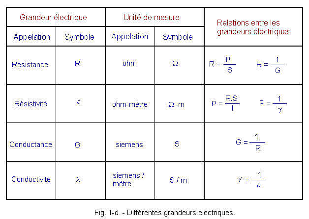
In the table of the figure 1-d are gathered the four sizes which we have just examined. For each one of them are
deferred the unit, the symbol corresponding and the relations existing between
these sizes.

Most important of these sizes without question resistance is because we can directly measure his value by
comparison with known elements, as we will see it in good time.
 2. - THE LAW
OF OHM
All the electric quantities relating to a circuit are now defined. We know the tension, the current (or intensity) and resistance.
We can pass on to the examination of a complete circuit and to see which influence have each one of these three sizes on its operation. Let us start with
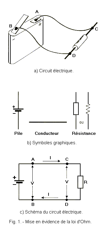
the very simple circuit such as it is represented figure 1-a).

This circuit consists of a resistance connected to a pile, the insertion of resistance is necessary so that the circuit presents
a well defined resistive value.
Appear 1-a, the circuit components are represented under their real aspect but during the examination of the electric
circuits one always considers the components under their aspect symbolic system. We thus obtain the electric diagram of the
circuit to be analyzed.
Appear 1-b are given the electric symbols of the three components of our circuit, while the figure 1-c appears its electric
diagram
The letters A, B, C
and D of the figures 1-a and 1-c indicate the points where the two drivers connecting the pile and resistance are welded
onto these two elements. The part of the diagram on the left of points A
and B represents the internal circuit of the pile while the part on the right of these same points represents the circuit
external with the pile, circuit consisted the drivers and resistance.
On the figure 1-c, we can indicate the various known electric quantities clearly.
The tension obtained at the boundaries of the
pile between the points A and B is indicated by its symbol V. This symbol is
registered between the two arrows which highlight point A and B, points between which appears this
tension.
The same tension V is also present at the terminals of resistance R,
that is to say between the point C and D, because the point (C) is connected directly
to the item (A) and thus has the same electric potential as this point ; it is the same with the point D directly
connected to B.
The resistance of the circuit external with the pile is located by its symbol R. One takes
account only of the resistive value of resistance and one neglects those of the drivers and the pile which are very weak. Lastly, the current which crosses the circuit is indicated by its symbol (I) with
the arrow showing the direction of its displacement following the conventional direction. We clearly see on this diagram that the current leaves the positive
pole of the pile, crosses the driver AC then resistance R and returns to the negative
pole of the pile via driver DB.
The existing tension V at the boundaries of the pile tends to cause the flow of current I
while resistance R presents an obstacle at its passage : it is understood that the intensity will depend on the
tension and resistance. In other words, it must exist a relation which binds between them these three fundamental electric quantities.
This relation was discovered by the German
physicist George Simon OHM (1789-1854) and was called law
of Ohm. The unit of resistance also bears the name of this physicist.
Ohm could state its law following many experiments and of meticulous measurements; to have an idea of the
process which it adopted, one can make some simple remarks.
As the tension of the pile is the cause which determines the flow of the current in the circuit, if
the tension is increased, one increases also the intensity of the current ; one can easily check this fact by successively connecting to the circuit piles
which give tensions increasingly higher and by measuring the intensity of the current that each one of them makes circulate, but one can go further.
Indeed, if one divides the tension of each pile by the intensity of the current which it makes circulate, one always finds the
same value; this value does not vary thus, although one varies the tension, and also consequently the intensity of the current.


 Electrical resistance concept
 Footer

.gif)


 Click here for the next lesson or in the summary provided for this purpose.