Examination of the Integrated Counter MM 74C163 and As Counter Modulo 10 :
6. - FIFTH EXPERIENCE : EXAMINATION OF THE INTEGRATED METER MM 74C163
With previous experience, you have examined a fairly complex synchronous counter circuit. Indeed, the latter consisted of several flip-flops and logic gates.
These synchronous or asynchronous counters exist in the form of integrated circuits.
In this experiment, you will examine one of these integrated circuits. This is the synchronous counter modulo 16 - MM 74C163.
It is a four bits counter that can have sixteen different combinations on its four outputs.
The MM 74C163 circuit has the advantage of being prepositionable on any combination of the meter.
Figure 13 shows the logic diagram of this circuit and Figure 14 the pinout diagram of this same circuit.
This circuit consists of four D flip-flops and a combinational network allowing a synchronous mode of operation.
You will discover in Figure 13 a new symbolization of logic gate. This is shown in Figure 15. This is the OR - Exclusive (EX - OR) function and the NOR - Exclusive (EX - NOR) function.
You notice that this counter is more advanced and more complex than the one discussed above.
It has indeed three additional entries and a new exit.
The ENABLE P and ENABLE T inputs (also noted as CEP and CET) are counter enable inputs. They must be at level H so that the circuit operates in counting mode.
They are used when multiple meters are connected in cascade.
To preposition the meter, three conditions are required.
First, the desired logic levels must be applied to the four inputs IN1, IN2, IN3 and IN4.
The LOAD input must also be at the L level.
Transfer to the four outputs will be done at the active edge of the clock.
The CLEAR entry is the reset entry. It is active at level L and makes it possible to level L the four outputs.
However, like the LOAD input, it is synchronous ; that is, an active clock pulse is required for it to be taken into account.
There is also the integrated circuit MM 74C161 which has the same characteristics. However, its entry CLEAR is asynchronous, acting as soon as it is brought to the level L.
The CARRY output is typically used when multiple meters are cascaded.
Indeed, it goes to level H when the four exits pass together at level H.
6. 1. - REALIZATION OF THE CIRCUIT
a) Remove all the links relating to the previous assembly, as well as the integrated circuits located on the matrix.
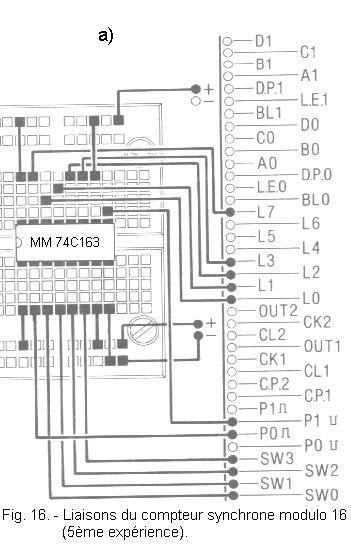
b) Insert the integrated circuit MM 74C163 on the matrix and make the connections shown in Figure 16-a.
The diagram of the realized circuit is shown (below) in Figure 16-b.
6. 2. - OPERATING TESTS
a) Turn on the digilab. The combination formed by the four LEDs is random. It depends on the physical characteristics of the integrated circuit.
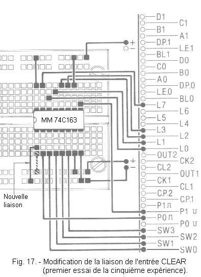
b) Move the link between pin 1 (CLEAR) and the positive voltage and connect this pin to the negative voltage (ground).
This is illustrated in Figure 17.
You notice that the state of the LEDs has not changed because the CLEAR input is synchronous.
c) Press P0. The four LEDs go out, so zeroing is done.
You have thus noted the synchronous operation of the reset.
Subsequently, you will find that the same applies to all the operations performed by this meter.
d) Re-establish the CLEAR
input link as shown in Figure 16-a. This input therefore returns to level H and so the counting phase can begin.
e) Press the P0 button fourteen times. At each pulse, the counter goes from one state to the next.
f) Press P0 one last time. This is the fifteenth clock pulse. The four LEDs are lit. LED L7 also lights up.
The counter arrived at maximum capacity, so the CARRY output has moved to level H.
g) Press P0 for the sixteenth time. The four LEDs go out, as well as the LED L7.
The counter has returned to its starting position, that is to say to zero. A new counting phase can begin.
h) Set the four switches to the following positions :
SW0 on position
0
SW1 on position
1
SW2 on position
0
SW3 on position
1
i) Press the P1 button. The LOAD input is therefore at the L level. However, the LEDs remain off because this input is synchronous, just like the CLEAR input.
While holding the P1 button in this position, also press P0. You observe that :
L0 is extinct
L1 is on
L2 is extinct
L3 is on
This indicates that the logic states on the four inputs IN1, IN2, IN3 and IN4 have been transferred to the four outputs of the flip-flops.
The counter is thus prepositioned in state 10, see 1010 in binary code.
Previously, you found that it was possible to pre-zero the counter by using the CLEAR entry.
In the latter case, the combination present on the four inputs IN1, IN2, IN3 and IN4 has no influence.
j) You can release both P1 and P0 buttons.
The counter can start a counting phase from 10.
k) Repeatedly press P0. At the fifth pulse, the LED L7 lights up.
Indeed, the counter has gone to 15 and the CARRY output has gone high.
With the sixth pulse the meter will go back to zero.
l) Turn off the digilab.
The meter examined in this experiment is one of the most complete.
Indeed, it has certain inputs and outputs that make it very flexible.
First, the LOAD input associated with the four inputs IN1, IN2, IN3 and IN4 makes it possible to preposition the counter on a given combination.
Then the CARRY output indicates that the counter has reached fifteen.
It allows with CEP and CET inputs to connect several meters to increase the overall capacity.
Finally, it is a synchronous counter and as such, it allows precisely these cascading assemblies using terminals CARRY, CEP and CET.
As you have learned in the
digital theory 9 and verified in this practice, a meter has a determined capacity.
This is the total number of combinations that outputs can take.
In the previous experiment, this number of combinations was sixteen.
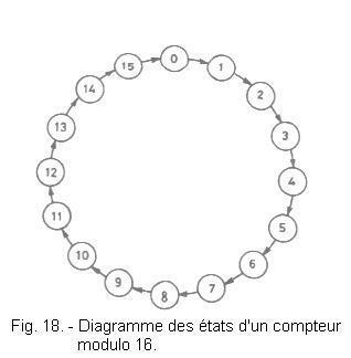
If you had started from a given combination (a given number), after sixteen pulses, you would have found the counter in the initial state.
This is shown schematically in Figure 18.
The arrows indicate the transition from one combination (one number) to the next.
Similarly, the diagram is a circle closed on itself, so it indicates that after sixteen clock pulses, the state of the counter is the same as the initial state.
With a modulo 16 counter, it is possible to realize a module counter between 2 and 16.
In this experiment, you will use the MM 74C163 circuit to realize a modulo 10 counter.
You will output combinations of 0 to 9.
Although it may seem paradoxical to limit the capacity of a counter, you will see that this principle is retained to obtain a divisor.
7. 1. - REALIZATION OF THE CIRCUIT
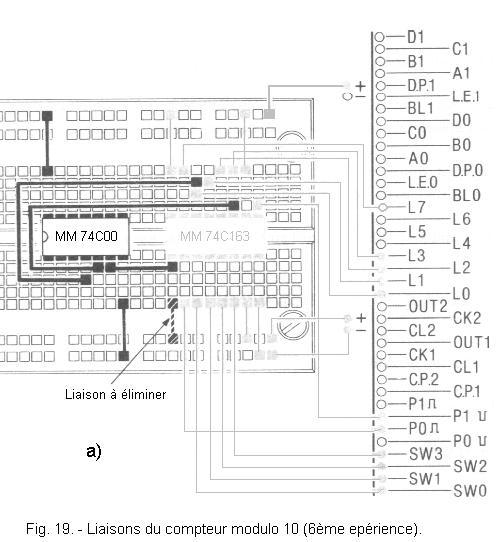
a) Insert on the matrix the integrated circuit MM 74C00 as illustrated in Figure 19-a.
b) Remove the connection between pin 1 of the integrated circuit MM 74C163 and the positive voltage.
Perform the connections shown in black in Figure 19-a.
The electrical circuit of the assembly carried out is given in Figure 19-b.
If you compare Figures 19-b and 16-b, you will see that a two inputs NAND gate has been added in this last mount.
Indeed, when the counter is at 9, the outputs Q1 and Q4 are in the high state and the entry CLEAR is in the low state, therefore is active.
At the next clock pulse, the counter is reset.
7. 2. - OPERATING TESTS
a) Turn on the digilab.
The counter is positioned on an unpredictable state.
b) Press P0 repeatedly until all four LEDs are off.
The counter is thus set to the zero state.
c) Keep pressing P0.
At the tenth pulse, the counter returns to zero.
The counter goes from state 0 to state 9 during the first nine clock pulses and returns to zero at the tenth.
You observe that the CARRY output remains permanently in state 0. Indeed, the counter does not go through state 15.
d) Turn off the digilab.
This experience has shown you how to get a modulo 10 meter with a modulo 16 meter using a NAND gate.
The state diagram of the modulo counter 10 is shown in Figure 20.
At power up, the circuit can optionally take a state between 10 and 15.
In any case, after six clock pulses at most, the counter will go into the state cycle from 0 to 9.
At that moment, it can only take one of the possible states between 0 and 9.
It should be noted that the CARRY output is never high and this can be a disadvantage.
In the next theory below, by clicking on the following link, you will see how to fix it.


 Using the MM 74C163 Circuit as a Modulo 10 Meter
 Click here for the next lesson or in the summary provided for this purpose.
 Top of page
 Next Page