Using Displays as a Count Indicator for a Modulo 16 Counter :
6. - THIRD EXPERIENCE : USE OF DISPLAYS AS A COUNTER INDICATOR FOR A MODULO 16 METER.
6. 1. - REALIZATION OF THE CIRCUIT
a) Remove all the connections relating to the previous experiment, as well as the integrated circuit MM 74C08 located on the ICX support.
b) Insert the integrated circuit MM 74C163 on the matrix and make the connections indicated in Figure 20-a.
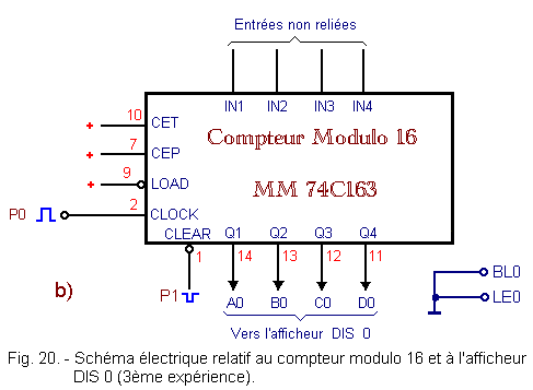
The outputs Q1, Q2, Q3 and Q4 of the meter are connected to the DIS0 display, according to the wiring diagram of Figure 20-b. The control inputs LE0 and BL0 of the display are connected to ground.
6. 2. - OPERATING TEST
a) Turn on the digilab.
b) Reset the counter by pressing P1 then P0 while holding both buttons simultaneously for a short time. Display DIS 0 appears as 0.
c) Repeatedly press P0 and observe DIS 0 every time. The display successively shows all the hexadecimal characters from 0 to F.
d) Turn off the digilab.
e) Prepare the clock generator on the frequency of 1 Hz. Remove the link coming from pin 2 of the contact counter P0
and insert it into contact CP1.
f) Turn on the digilab. The counter counts cyclically from 0 to 15 at the clock frequency. The display also shows all the hexadecimal characters from 0 to F cyclically at the rate of one character per second.
g) Turn off the digilab.
7. - FOURTH EXPERIENCE : USE
OF A DECODER 4 INPUTS - 10 OUTPUTS TO REALIZE A DIVIDER BY 10
Sometimes it is necessary to have a variable module counter.
In the previous practice, you have seen how it was possible to realize a given module counter, using the module MM 74C163 counter 16.
In this experiment, you will use the integrated circuit MM 74C42.
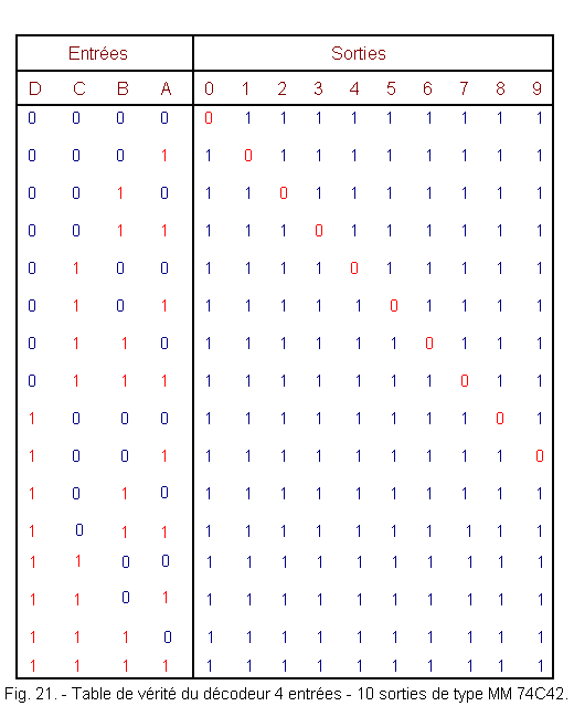
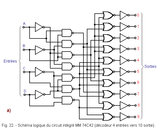
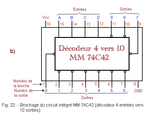
This is a 4 inputs / 10 outputs decoder whose truth table is located in Figure 21 and the logic diagram and pinout in Figure 22.
7. 1. - REALIZATION OF THE CIRCUIT (FIRST TEST)
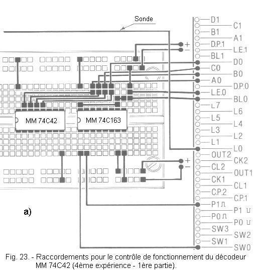
a) Remove from the matrix the links and the integrated circuit related to the previous experiment.
b) Insert the integrated circuits MM 74C163 and MM 74C42 on the matrix and make the connections as shown in Figure 23-a.
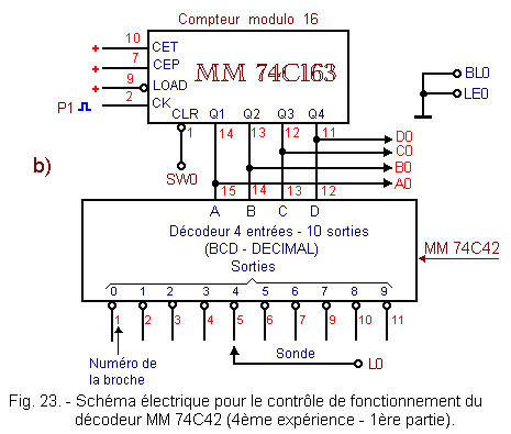
The electrical diagram of the realized circuit is given in Figure 23-b.
7. 2. - FIRST TEST OF OPERATION
You will check the operation of the decoder.
a) Turn on the digilab.
b) Set SW0 to the 0 position.
c) Press P1. The counter is reset. The DIS0 display indicates 0.
d) Check with the sensor that output 0 of the decoder is at level L (LED L0 is off).
e) Put SW0 on position 1.
f) Press P1.The number 1 appears on the display.
g) Check that output 1 of the decoder is at level L.
h) Continue to press P1.
You notice that when the display shows the hexadecimal characters from A to F, none of the outputs of the decoder is at level L.
i) Turn off the digilab.
7. 3. - REALIZATION OF THE CIRCUIT FOR THE SECOND TEST
In this second part of the experiment, the decoder is used to reduce the counter module.
a) Remove the following links :
that located between the pin 1 of the counter MM 74C163 and SW0.
that located between the pin 2 of the meter and the contact P1.
the contact probe L0.
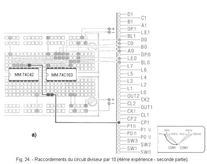
b) Make the two new connections as shown in Figure 24-a.
Thus, the output 9 of the decoder is connected to the input CLEAR of the counter. The counter's CLOCK input is connected to the CP1 contact. The electrical diagram of the new circuit is located in Figure 24-b.
7. 4. - TEST OF OPERATION
a) Turn on the digilab.
On the display, you can scroll at a rate of one per second from 0 to 9 cyclically.
The meter module has thus been increased from 16 to 10.
When the counter goes to state 9, the corresponding output of the decoder goes to level L. So the CLEAR input of the counter is brought to the level L.
At the next active edge of the clock, the counter goes to 0.
b)If you connect the CLEAR input of the meter successively to the different outputs of the decoder, you change the meter module each time.
This module can therefore vary from 2 to 10 in the present case.
c) Turn off the digilab.
To conclude, this experiment shows that it is possible to use a decoder to vary the module of a counter.
For this purpose, it is the CLEAR input of the counter which is used as in experiment 6 of practice 9.
Indeed, it is sufficient to modify the connection between the input CLEAR and one of the outputs of the decoder to change the module of the counter.
On the other hand, if you replace the decoder MM 74C42 by the one used in the second experiment (practice 10), you can obtain a counter whose module varies between 2 and 16.


 Using a Decoder 4 to 10 to achieve a Divider by 10
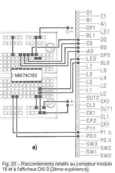

 Click here for the next lesson or in the summary provided for this purpose.
 Top of page
 Next Page