Definition and Function of a Counter :
This theory presents all the digital circuits used for counting and counting functions.
1. - DEFINITION AND FUNCTION OF A COUNTER :
A counter (or up-counter) is an electronic circuit consisting essentially of a set of flip-flops and most often a combinatorial network.
This counter (or down counter) counts the number of events that occur during a given time.
Each event is translated into an electrical pulse.
These circuits usually have an input (sometimes two inputs) on which pulses to count or count down.
The information available is located on all the outputs of the scales.
There are many applications of the meters.
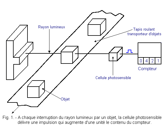
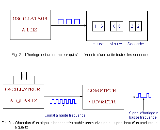
We can mention the counting of objects (Figure 1), the measurement of time (Figure 2), the division of time for obtaining clock signals for the control of synchronized systems (Figure 3).
Note :
A counter whose content increases by one increments.
A down-counter whose content decreases by one is decremented.
There is a wide variety of counters that you will discover in the next chapters.
2. - ASYNCHRONOUS BINARY COUNTERS
Asynchronous binary counters use pure binary code to count (or count down).
These counters are asynchronous because only the first flip-flop receives the clock signal.
All flip-flops that follow it are controlled by the previous flip-flop as shown in Figure 4.

2. 1. - COUNTER / DIVIDER BY TWO
The assembly in Figure 5 is the simplest counter since it only uses a D-type flip-flop and is able to count only one event.
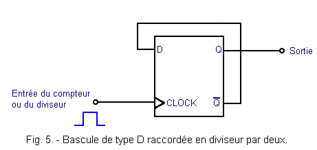
The exit ![]() is looped back on the entry D.
is looped back on the entry D.
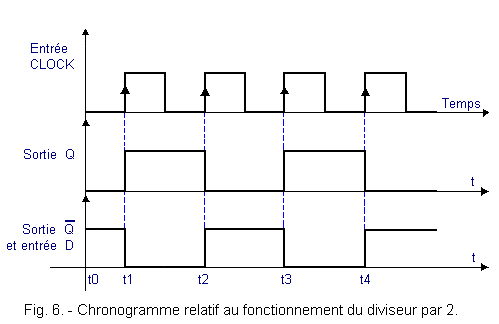
The timing diagram of Figure 6 makes it possible to follow the evolution of the clock signals and the outputs Q and ![]() .
.
Suppose that the output Q is at the level L at time t0, so ![]() and D at level H.
and D at level H.
At time t1 the first active edge occurs. The output Q switches to level H since the input D is at level H.
Between instants t1 and t2, input D is at level L. Thus, at time t2, Q returns to level L and D to level H. At time t3, Q returns to level H and so on.
The period of the signal which is present on the output Q is thus twice that of the clock signal.
In other words, the frequency of the output signal is half that of the clock signal. It is for this reason that this assembly is a divider by 2.
It is the basic element of most counters.
This counter has two states, which are 0 and 1, the state of a counter being defined by a particular combination of the logic states of the different outputs. This counter can detect only one pulse, provided to set the initial state of the rocker.
We will see that there is a problem with the delay inside the flip-flop.
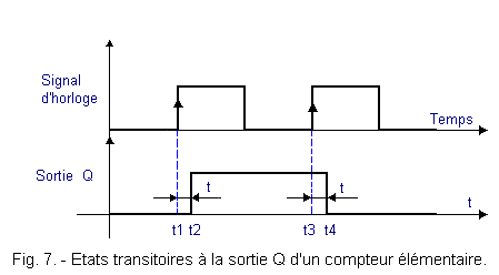
Indeed, if you look at Figure 7, you notice that there is a transient state between times t1 and t2 and between times t3 and t4.
We will come back to this problem during this theory.
A divisor by two can also be obtained with a JK flip-flop as shown in Figure 8.

This flip-flop works in TOGGLE mode. The timing diagram is the same as that relating to the flip-flop D located in Figure 6. This TOGGLE operating mode was presented during theory 5.
2. 2. - A MODULO COUNTER 4
The assembly located in Figure 9 is a counter constituted from two D flip-flops.
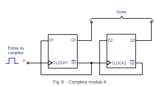
This assembly is an asynchronous counter since the clock signal H is only applied to the CLOCK input of the first flip-flop (CLOCK1).
The output ![]() 1
is connected to the CLOCK input of the second flip-flop (CLOCK2).
1
is connected to the CLOCK input of the second flip-flop (CLOCK2).
Each flip-flop is wired as a divider by two.
The timing diagram of Figure 10 makes it possible to follow the evolution of the meter over time.
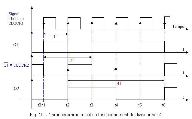
At time t0, the two outputs Q1 and Q2 are at the level L.
At the first active clock edge (time t1), the output Q1 switches and goes to level H. ![]() 1
goes to level L.
1
goes to level L.
At time t2, Q1 goes back to L and ![]() 1
level H, so an active edge is applied to the clock input of the second flip-flop. Q2 therefore goes to level H.
1
level H, so an active edge is applied to the clock input of the second flip-flop. Q2 therefore goes to level H.
At time t3, Q1 returns to level H and Q2 remains at level H.
At time t4, Q1 returns to level L and Q2 also. Both outputs have returned to their original state. It took four clock pulses to recover the initial state of the two flip-flops.
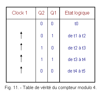
The truth table in Figure 11 summarizes the evolution of the counter and the divider by 4.
This counter is of module 4. The module is the number of logic states formed by all the outputs of the counter.
In the present case, it is a counter having four logical states (00, 01, 10, 11) in binary code or 0, 1, 2 and 3 in decimal code).
The capacity of this counter is 3. The capacity is the maximum number of events that a counter can count. It is always equal to the module minus one since during the initial state (here 00) no event has yet been taken into account.
The output Q1 divides the frequency of the clock H by two and the output Q2 divides by four the same frequency of the clock H. In Figure 10, it appears that the period of the output signal Q1 is twice the period of the clock and at the output Q2 the period of the signal is worth four times the period of the clock.
In general, it is always possible to use one or more outputs of a counter to have a division of the frequency of the clock In the clock in Figure 2, this property is used to count the elapsed time.
In fact, the signal of the 1 Hz frequency clock is divided by 60 and makes it possible to obtain a 1 minute period signal. This second signal is in turn divided by 60 in order to obtain the 1 hour period signal. Then just count the hours to 24 for one day to pass.
![]() 2. 3. - METERS OF MODULE SUPERIOR TO FOUR
(Return to 9TS theory)
2. 3. - METERS OF MODULE SUPERIOR TO FOUR
(Return to 9TS theory)
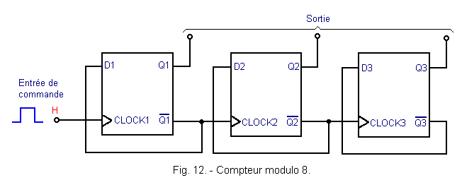
By connecting three flip-flops D as shown in Figure 12, a module counter 8 is obtained.
Three D flip-flops wired as a divider by 2 are used.
The timing diagram of Figure 13 makes it possible to understand the operation of this counter. The operating principle is always the same.
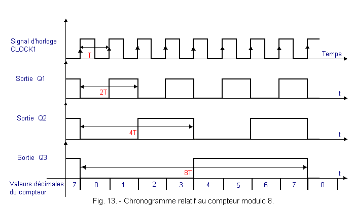
Each stage divides by 2 the signal applied on its clock input. On the Q3 output, the signal that can be taken is therefore at a frequency 8 times smaller than the clock signal.
In general, it is therefore possible to increase the module of an asynchronous counter by increasing the number of flip-flops. With a new flip-flop, the double module.
If a counter has n flip-flops, its maximum module is 2n. For n = 4, the module is 16, for n = 5, it is 32, ...
It is possible to obtain an odd module counter (3, 5, 7 ...) using the same types of assemblies as those seen previously. This will be presented later.
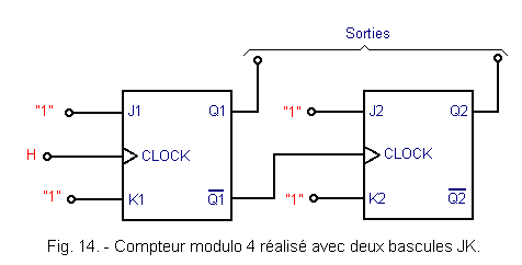
In addition, it is possible to replace each D flip-flop by a JK flip-flop wired in TOGGLE mode (the J and K inputs are wired to «1»). Figure 14 represents a modulo 4 counter made with two JK flip-flops.
We will return to the problem of transient states. Figure 15 represents a part of the operating chronogram of a modulo 8 counter.
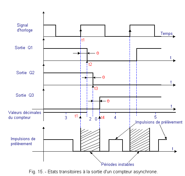
On this chronogram, it appears that the duration of unstable periods (transient states) is a function of the number of flip-flops. This duration is at most t4 - t1 = 3q in the present case.
During this unstable period (t4 - t1), instead of going directly from state 3 to state 4, the counter successively passes through transient states 2 and 0. It is considered here that the delay of each flip-flop is substantially the same (q). In reality, these three propagation times may be different.
It is obvious that if the number of flip-flops increases, the duration of the unstable period also increases. This is due to the asynchronous operation of the counter since the latches react on each other in cascade.
For this reason, a sampling pulse is used to «read» the state of the meter. This pulse will be shifted with respect to the clock signal of a duration greater than that of the transient states. This pulse can be generated using a monostable.
Figures 16 and 17 show two schemes for taking the contents of a meter.
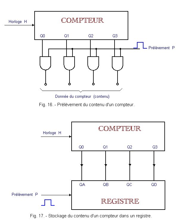
In the case of Figure 17, it is also possible to store the content of the counter in the register during the period that is desired.
These transient states are therefore one of the main factors that will limit the clock frequency of the counter.
In MOS technology, with q = 100 ns, and 4 D flip-flops, the period of transient states is about 400 ns. If you reserve about 100 ns extra to collect the contents of the meter, the maximum operating frequency will be 2 MHz :

If you want to work at a relatively high frequency and use a high capacity counter, you will have to use a synchronous counter.
![]() 2. 4. - PRESENTATION OF TWO
INTEGRATED COUNTERS
2. 4. - PRESENTATION OF TWO
INTEGRATED COUNTERS
2. 4. 1. - THE INTEGRATED COUNTER 7493
Figure 18 represents the schematic diagram of the integrated counter 7493 made in TTL technology as well as its pinout.
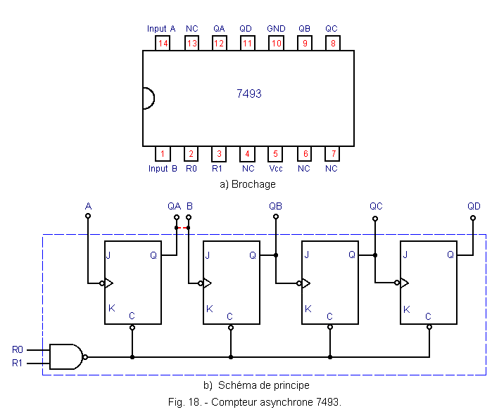
The block diagram
is the same as that of Figure 14. J and K flip-flop inputs are wired internally to «1».
A general asynchronous reset of the counter is possible thanks to the inputs R0 and R1. For this, the two inputs R0 and R1 must be simultaneously «1».
This counter can operate as a divider by 8 by presenting the clock on the input B or divide by 16 by presenting the clock on the input A and connecting the output QA to the input B.
2. 4. 2. - THE INTEGRATED COUNTER 4024
Its block diagram and pinout are given in Figure 19.
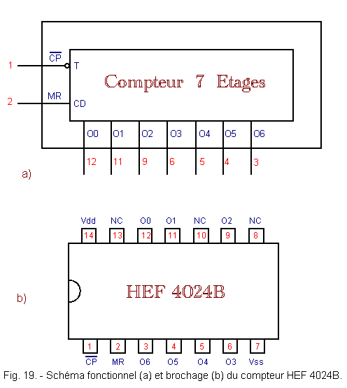
This circuit is made in MOS technology. The symbol «N.C.» means «not connected».
It is a seven-stage binary counter cascading. His logic diagram is given in Figure 20.
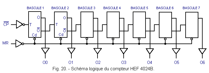
![]() is the clock input. MR is the priority asynchronous reset priority entry. The presence of a level H on MR resets all stages of the counter to zero independently of
is the clock input. MR is the priority asynchronous reset priority entry. The presence of a level H on MR resets all stages of the counter to zero independently of ![]() . This counter is incremented on the falling edge of
. This counter is incremented on the falling edge of ![]() and can count up to 27 - 1 = 127 pulses.
and can count up to 27 - 1 = 127 pulses.
 Click here for the next lesson or in the summary provided for this purpose. Click here for the next lesson or in the summary provided for this purpose. |
|
 Previous Page Previous Page |
 Next Page Next Page |
Nombre de pages vues, à partir de cette date : le 27 Décembre 2019
Envoyez un courrier électronique à Administrateur Web Société pour toute question ou remarque concernant ce site Web.
Version du site : 10. 4. 12 - Site optimisation 1280 x 1024 pixels - Faculté de Nanterre - Dernière modification : 02 Septembre 2016.
Ce site Web a été Créé le, 14 Mars 1999 et ayant Rénové, en Septembre 2016.
 Four-Up Module Counters