 Synchronous integrated counter : the 4520 Synchronous integrated counter : the 4520 |
 Counters-divisors by ''n'' Counters-divisors by ''n''
|
 Integrated meter modulo 10 : the 7490 Integrated meter modulo 10 : the 7490
|
 Footer Footer |
Synchronous Binary Counters :
3. - SYNCHRONOUS BINARY COUNTERS
3. 1. - DEFINITION
These are counters (down-counters) whose all stages (flip-flops) are controlled by the same clock signal.
This operating mode makes it possible to limit the duration of the periods of instability and consequently allows higher operating speeds than in asynchronous mode.
3. 2. - MODELS OF SYNCHRONOUS COUNTERS
3. 2. 1. - MODULO COUNTER 4
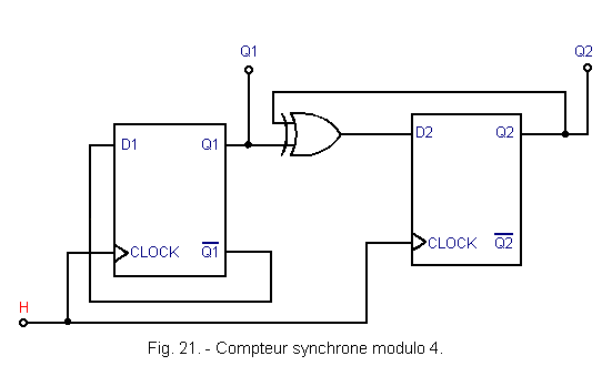
This counter made with two D flip-flops is shown in Figure 21.
If you look at the truth table in Figure 11, you will see that output Q1 alternately changes from state «0» to state «1» at each active edge of the clock H.
Thus, the output Q1 of this divider by two may be the least significant bit (LSB) of the counter. The first D flip-flop of a counter operating in binary code will moreover always be wired as a divider by two. The output Q2 of the second flip-flop of the modulo 4 counter must provide, for its part, the most significant bit (MSB), which is represented in Figure 22.
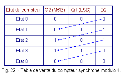
Depending on the state of Q2 that is imposed, let's see what the state of the corresponding D2 entry should be.
If the counter is in state 0 (outputs Q1 and Q2 in the state «0»), the input D2 must be in the state «0» since at the next clock edge, the output Q2 must remain in the state «0». This is symbolized by an arrow in Figure 22.
When the counter is in state 1 (output Q1 to «1» and Q2 to «0»), D2 must be in state «1» since Q2 must pass to «1» at the next active clock edge and and so on ...
From this table of truth, one writes in the table of Karnaugh of Figure 23.
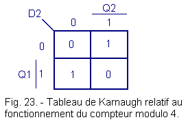
We can deduct :
D2 = Q1.![]() 2
+
2
+ ![]() 1.
Q2 = Q1
1.
Q2 = Q1 ![]() Q2
Q2
This is the EXCLUSIVE OR, which appears in the assembly of Figure 21.
3. 2. 2. - UPPER MODULE METERS AT FOUR
According to the same principle, Figure 24 represents a synchronous module counter 8 made with 3 D flip-flops.
In this arrangement, there are two additional doors compared to that of Figure 21.
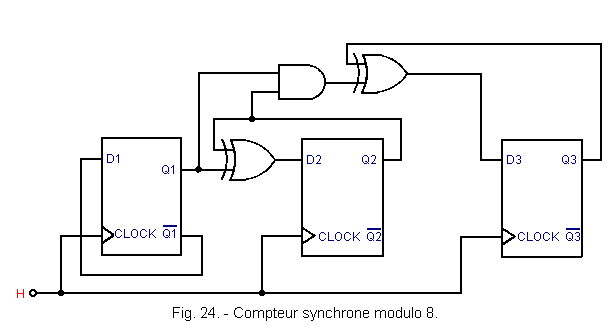
The third rocker only switches in two cases :
![]() First, if both outputs Q1 and Q2 are in state «1» and the output Q3 in state «0». The counter in this case indicates
0112
= 310 and must be changed to 1002
= 410.
First, if both outputs Q1 and Q2 are in state «1» and the output Q3 in state «0». The counter in this case indicates
0112
= 310 and must be changed to 1002
= 410.
![]() Then it switches when the counter is at 1112
= 710
and should go to 0002
= 010.
Then it switches when the counter is at 1112
= 710
and should go to 0002
= 010.
To realize these two conditions, it is necessary to use two additional doors : an AND gate which receives the outputs Q1 and Q2, and an EXCLUSIVE OR gate receiving the output Q3 and the output of the AND gate.
To produce a synchronous module counter 16, it is necessary to add an additional flip-flop. Thus, we are led to the diagram of Figure 25.
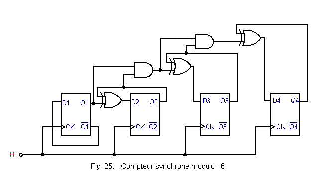
Compared to the previous installation, this one has two additional doors : a two-input AND gate and an EXCLUSIVE OR gate.
You note first that the scheme is complicated with the increase in the number of flip-flops. You notice that a flip-flop is zero, it only goes to «1» if all the previous latches are at «1». This explains the use of AND gates.
It would be possible to add new scales to increase the capacity of the meter. Nevertheless, the scheme would quickly become very complex, so it will be better to use counters in integrated circuits.
It is possible to calculate the operating speed of a synchronous module counter 16.
If we take again the same values as in chapter 2. 3., namely q » 100 ns and if one always reserves 100 ns to take the contents of the counter, one reaches a frequency limit :

We can note that during the 100 ns reserved for sampling, the combinational network formed by the AND and EXCLUSIVE OR gates has time to stabilize.
In reality, the synchronous integrated counters allow much higher operating speeds than the one calculated here.
![]() 3. 2. 3. - AN INTEGRATED
SYNCHRONOUS METER : THE 4520
3. 2. 3. - AN INTEGRATED
SYNCHRONOUS METER : THE 4520
The HEF 4520 B integrated circuit is made of MOS technology.
It includes a double 4-bit synchronous binary counter. Its mimicry and its pinout are given in Figure 26 and the logic diagram of a counter in Figure 27.
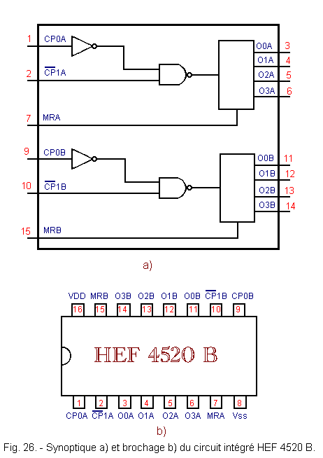
Each counter includes an active clock input on a rising edge (CP0) and an active clock input on a falling edge (![]() 1).
1).
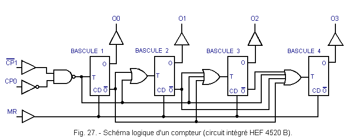
There is an asynchronous MR reset input for each counter. It is a priority and active at the high level. It is possible to use one of the two clock inputs as the enable input while the other receives the clock signal.
![]() 4. - THE COUNTERS -
DIVIDERS
BY n
4. - THE COUNTERS -
DIVIDERS
BY n
4. 1. - THE DIAGRAM OF STATES
The state of a counter is the particular combination formed by all the outputs of this counter. A modulo 2 counter has two states. Its only output is either «0» or «1». A modulo 4 counter has 4 states. Its two outputs can realize 4 different combinations (00, 01, 10, 11).
The diagram of the states of a counter makes it possible to represent all the states that this counter can take. Figure 28 shows the state diagram of a modulo 4 counter.
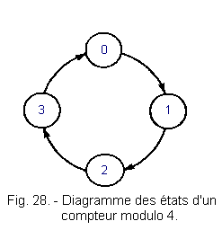
In this diagram, each state is represented by a decimal number in a circle. The arrows represent the direction of «course» of the meter.
The state diagram can also be represented as shown in Figure 29.
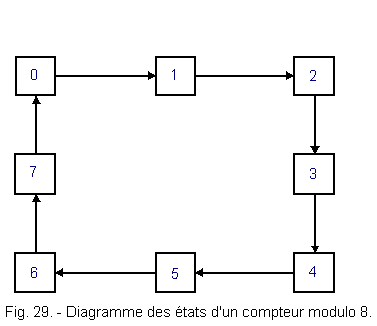
In general, we say that a counter has n states, or that it is a divider by n. This is called counter-divisor by n.
At each pulse on the clock input the counter goes from one state to the next in the order given by the state diagram.
4. 2. - COUNTER NOT USING THE BINARY CODE
So far, you have seen counters using the binary code, but there are also counters using other codes.
This is the case of the Johnson meters, an example of which will be presented in the following theory, since these meters use a decoding circuit.
Figure 30 shows the state table of such a five-stage counter. This is the counting circuit of the integrated circuit HEF 4017 B realized in MOS technology.
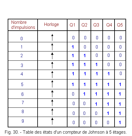
These five outputs Q1, Q2, Q3, Q4 and Q5 are outputs of flip-flops, internal to the integrated circuit, and therefore, are not accessible.
This counter uses the principle of a shift register looped back on itself.
Indeed, during the first clock pulse, the output Q1 goes to state «1» then, this state «1» shifts from Q1 to Q5. Once output Q5 is changed to state «1», The output Q1 returns to state «0» at the next active clock edge. In total, this counter has ten states and can count nine pulses.
4. 3. - COUNTER A VARIABLE MODULE
Until now, you have seen counters whose module is a power of 2 (2, 4, 8, 16, ...). However, it may be necessary to have counters whose module is any integer (3, 5, 7, 9, 10, ...).
It is then necessary to modify the counting circuits seen until now. Figure 31 presents a synchronous modulo 3 counter made with two D flip-flops.
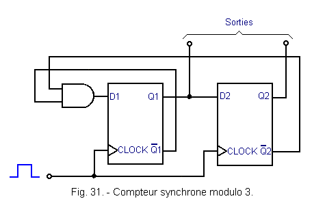
The operating chronogram and the state diagram are shown in Figure 32.
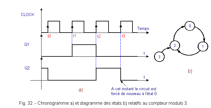
Suppose the counter is in state 0. Q1 and Q2 are in state «0», so ![]() 1
and
1
and ![]() 2
are in state «1» and D1 is in state «1».
2
are in state «1» and D1 is in state «1».
At time t1, the counter goes to state 1 (Q1 = «1» and Q2 = «0»). At time t2, the counter goes to state 2 (Q1 = «0» and Q2 = «1»).
At this time, D1 = «0» and not «1» as in the case of the modulo 4 counter. So at t3, the counter is «forced» to state 0 and does not go through state 3.
At power up, it may happen that the counter is set to state 3. In this case, it returns to state 2 at the first rising clock face and, therefore, it remains in the ring of three states (0, 1 and 2) without ever returning to state 3.
This counter is a counter with incomplete cycle and synchronous reaction. Indeed, the cycle is incomplete since two D flip-flops allow 22 = 4 different states and one uses 3 in this case.
On the other hand, the reaction is synchronous since the AND gate decodes the state 2 (102 = 210) and the reset takes place at the active clock edge.
There are also incomplete cycle counters with asynchronous feedback.
If the counter must return to 0 after the N state, it is sufficient to decode the N + 1 state, which makes it possible to reset the counter to 0 by acting on the asynchronous CLEAR input. An example is given below.
4. 4. - SYNCHRONOUS AND ASYNCHRONOUS DECADES
Decades are counters with 10 stable states. These are counters that are commonly encountered. Indeed, they allow to directly materialize the decimal numeration.
We will see two models of decades made with discrete scales and an integrated counter.
4. 4. 1. - ASYNCHRONOUS DECADE
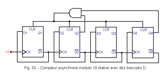
His diagram is given in Figure 33.
The timing diagram of Figure 34 allows to understand the operation.
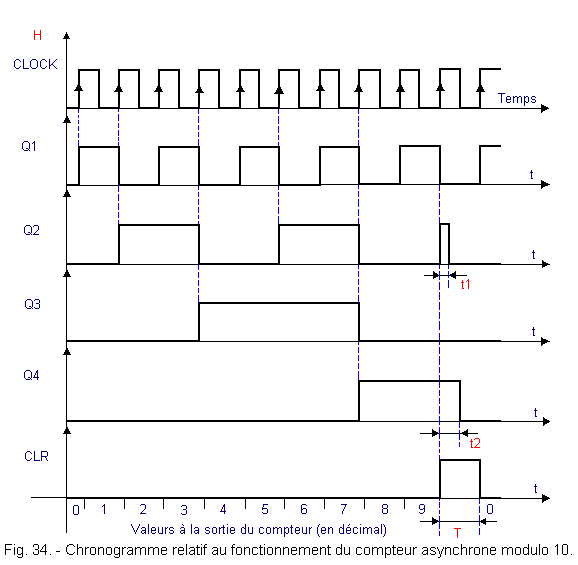
This assembly is an example of an incomplete cycle counter with asynchronous feedback.
Indeed, in the present case, it is the state 1010 (10102) which is decoded using the AND gate and which allows the general reset of the four flip-flops.
Nevertheless, this assembly poses a certain number of problems of operation :
![]() First, it is necessary that T is greater than t1 and t2, so that the resetting of the flip-flops is very fast (T is the duration of the reset pulse at the output of the AND gate).
First, it is necessary that T is greater than t1 and t2, so that the resetting of the flip-flops is very fast (T is the duration of the reset pulse at the output of the AND gate).
Indeed, if the reset pulse returns to the 0 state before one of the latches (here the second and the fourth) has been ironed to zero, the latter will remain in the state «1».
If, for example, the period t1 is very short and t2 is very long and moreover the propagation time through the AND gate is also very short, the output Q4 can remain in state «1», so the counter will pass from state «9» to state «8», then return to state «9» and so on ...
Practically, delays must be introduced by RC cells placed at the input of the ET as shown in Figure 35.
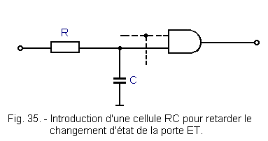
Then, the AND gate can detect the aforementioned transient states (paragraph 2. 3.) and make the operation of the set unpredictable.
As a general rule, it will be necessary to be very attentive to the choice of the components and to the realization of this type of circuit.
4. 4. 2. - A SYNCHRONOUS DECADE
The diagram of Figure 36 is that of a synchronous decade realized with type 7472 JK flip-flops.
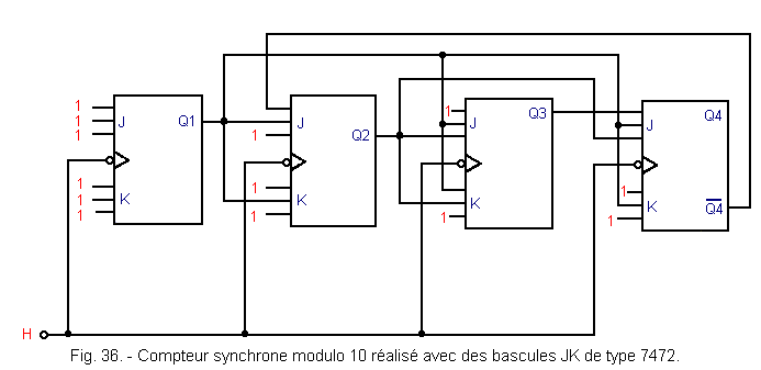
Recall that the three inputs J, as well as the three inputs K end on an AND gate. That's why unused entries are connected to «1».
With this synchronous mount, the problems encountered with the asynchronous decade no longer exist.
![]() 4. 4. 3. - AN INTEGRATED METER MODULO 10 : THE 7490
4. 4. 3. - AN INTEGRATED METER MODULO 10 : THE 7490
It is a very used meter. His diagram is given in Figure 37.
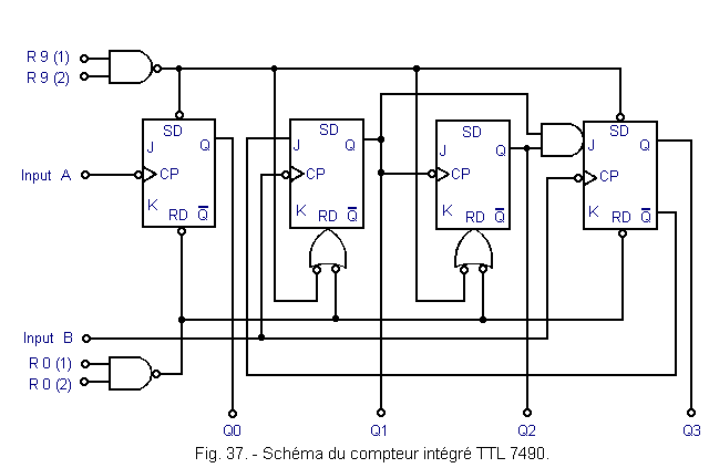
This counter is made in TTL technology. Its pinout is given in Figure 38. The symbol «NC» means «not connected».
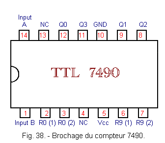
This circuit has two sections. A divider section by 2 and a divider section by 5.
It is possible either to use them separately, or to combine them together to obtain a BCD modulo 10 meter or a divider by 10.
The first divider by 2 section is constituted by the first flip-flop JK whose clock input is denoted «INPUT A» and the output «Q0». The unconnected J and K inputs on the schematic are all connected to logic level H.
The second section has the following three JK flip-flops. The clock input is denoted «INPUT B» and the three outputs are Q1, Q2 and Q3. This third output Q3 delivers a signal divided by 5 with respect to the clock signal applied to the input «INPUT B».
This modulo 5 counter uses the binary code.
To obtain a modulo 10 counter in BCD code, simply connect the Q0 output to the INPUT B input. The Q0 output which halves the clock frequency itself controls the divider section by 5. It is therefore possible to collect a signal at the output Q3 whose frequency is 1 / 10th of that of the clock.
The truth table in Figure 39 makes it possible to specify the general operation of this counter.
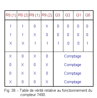
The two inputs R9 (1) and R9 (2) make it possible to preposition the counter in state 9. These inputs have priority over the reset inputs (R0 (1) and R0 (2)).
SD is the set entry to «1» and RD is the set entry to «0».
There is a second possibility to connect the two sections. This is to connect the Q3 output to the input «INPUT A». This makes it possible to collect a signal whose frequency is always 1 / 10th of that of the clock but this time, the signal has a duty cycle equal to 1 / 2. This appears in Figure 40.
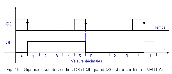
On the other hand, with this connection, the four outputs do not use the BCD code. The resulting counter counts as 0, 1, 2, 3, 4, 8, 9, A, B, C.
 Click here for the next lesson or in the summary provided for this purpose. Click here for the next lesson or in the summary provided for this purpose. |
|
 Previous Page Previous Page |
 Next Page Next Page |
Nombre de pages vues, à partir de cette date : le 27 Décembre 2019
Envoyez un courrier électronique à Administrateur Web Société pour toute question ou remarque concernant ce site Web.
Version du site : 10. 4. 12 - Site optimisation 1280 x 1024 pixels - Faculté de Nanterre - Dernière modification : 02 Septembre 2016.
Ce site Web a été Créé le, 14 Mars 1999 et ayant Rénové, en Septembre 2016.
