Operation Control of the 840 Contacts Matrix :
3. - OPERATING CHECK OF THE 840 CONTACTS MATRIX
Make sure that the assembly of the finished digilab is as shown in Figure 3. Then perform a power off of the matrix as follows :
3. 1. - OFF-VOLTAGE CONTROL
 Strip both ends of a piece of insulated tinned wire and insert one end into the first contact at the bottom right of the first 25 contacts line (Figure 10).
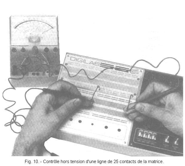
In the same way, prepare the ends of a second insulated tinned wire and insert one end into the last contact on the left of the same line of contacts.
Place the controller on the Ω x 1000 gauge and put the test tips in contact with the free ends of the two wires. The needle indicates a resistance of 0 Ω confirming that the two contacts in question are electrically connected.
Put the two wires in the extreme contacts of the line just above the one you have just checked and check that in this case also the ohmmeter indicates a resistance of 0 Ω.
Proceed in the same way, check the continuity between the extreme contacts of the remaining contact lines.
Perform a similar check on the 5 contacts columns. Full control would require verification of all rows and columns and all contacts making up the matrix. However, a control of the connection between the first and the last contact of each row and column is sufficient to be normally ensured of the proper functioning of the matrix.
3. 2. - CONTROL ON VOLTAGE
Prepare the ends of six pieces of black insulated tinned wire and as many pieces of red insulated wire of appropriate length and make the connections shown in Figure 11. Note that the red wire is used for contact line connections resulting in contact "+" while the black wire is used for the contact lines connected to the "-" contact.
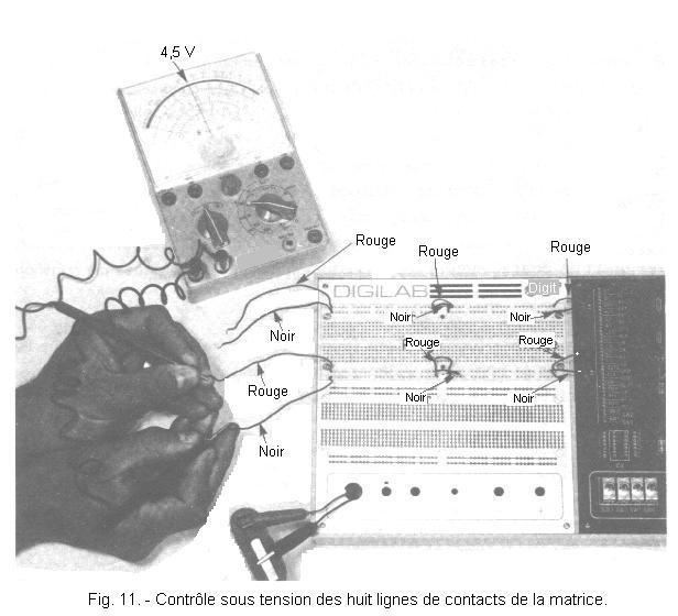
Make sure that the free ends of the pieces of wire connected to the last contacts to the left of the two upper and lower lines are insulated from each other. Power the circuit by connecting the two red and black alligator clips respectively to the (+) and (-) poles of the 4.5 V battery.
Place the voltmeter on the 10 V continuous gauge and contact the end of the red wire (connected to the second line of contacts from the bottom) with the red test point. Put the black tip into contact with the end of the black wire of the first line of contacts as shown in Figure 11. The needle should indicate a voltage equal to that of the battery is about 4.5 V.
Perform the same check on the top four lines of contacts, putting the red and black hitters in contact with the ends of the red and black wires connected at the end of these lines. In this case too, you need to obtain a voltage of about 4.5 V.
The connections made during this check are those that are usually done for the use of the matrix. In this way, indeed, the voltages (positive and negative or mass) are available on the upper side as on the lower side of the matrix thanks to the eight lines of contacts. This will be very convenient for powering the circuits mounted on the contact columns located in the central area of the matrix.
The use of the red and black connection wires respectively for the positive and negative supply lines makes it possible to distinguish these immediately.
Be sure to always follow this convention even if it is not specifically indicated later.
Having completed the control of the contact matrix, you can proceed to the realization of the experiments planned for this practice.


 Footer
 Click here for the next lesson or in the summary provided for this purpose.
 Top of page
 Next Page