In the first part of this practice, you will continue building your digilab, adding next to the printed circuit board used in previous experiments, a special plate for experimental setup called BREADBOARD (matrix or plate with 840 contacts that you can be found in the various electronics specialty stores) which will greatly expand the possibilities of using the digilab.
You will then carry out a series of experiments with which you will complete your knowledge of the scales and will examine in particular the operation of the J.K flip-flop.
By using the scales in your possession, you will finally realize two simple circuits of application.
1. - PREPARATION OF EQUIPMENT
In this practice, you will use the following material :
1 box for the digilab
(35 x 19 cm)
1 partition wall for the digilab cabinet
1 aluminum front for the box (17 x 18 cm)
1 plate or matrix of 840 "Breadboard" contacts (16,5 x 5,5 cm)
1 self-adhesive label of the links of the matrix with 840 contacts (sold with the matrix)
8 self-tapping screws of 2,2 x 9,5 mm
4 countersunk screws Ø 3
x 14 mm
4 nuts Ø 3
1 integrated circuit CD 4042 or its equivalent
2 integrated circuits MM 74C00 or its equivalent
1 integrated circuit MM 74C04 or its equivalent
1 integrated circuit CD 4027 or its equivalent
1 integrated circuit MM 74C08 or its equivalent
2 integrated circuits MM 74C74 or its equivalent
1 braid of tinned wire insulated black
1 braided red tinned wire
Let's see what are the characteristics of the contact matrix.
The matrix with contacts (Figure 1-a) is a plate specially designed to allow very fast realization of experimental electronic assemblies without having to resort to the use of the soldering iron. It consists of a base of synthetic insulating material, in which is incorporated a matrix of 840 spring contacts of high quality. These contacts are accessible from the outside through as many opening holes made on the insulating support. These holes are at standardized pitch of 2.54 mm.
The contact matrix makes it possible to insert all the electronic components, the discrete ones whose terminals have a maximum diameter of 0.8 mm like those integrated into T05, DIL or DIP boxes from 8 to 64 pins.
The contacts are made of no corrosive silver nickel alloy and each of them is guaranteed up to 10 000 insertion cycles using wire 0.6 mm in diameter. The nominal resistance of each contact is 5 mΩ, while the inductance and parasitic contact contact capacity are negligible up to 30 MHz.
The different contacts of the matrix are grouped together as indicated on the self-adhesive label and represented in Figure 1-b.
In the central zone, there are 128 groups of 5 electrically connected contacts arranged in columns (64 groups above and 64 groups below the median groove on the support).
The integrated circuits can be inserted astride the central groove as you can see in Figure 2. The matrix can thus receive up to eight 14 pins integrated circuits DIL and for each of them, there are four contacts available to make the electrical connections.
There are then eight groups of contacts, each consisting of 25 electrically connected contacts, arranged in line lengthwise on both sides of the matrix as you can also see in Figure 1-b. They are intended for the connections of the power supply, the masses and the various controls of the main circuits mounted on the central zone of the matrix.
IMPORTANT NOTE :
The duration and reliability of the contacts in the matrix are subject to compliance with the following usage standards :
never insert conductors or component terminals with a diameter greater than 0.8 mm into a contact because they could easily damage the contact springs.
always ensure that the ends of the conductors or terminals of the components to be inserted into the contacts of the die are not damaged by bending, scratching or solder residue.
when making the connections, exert a correct pressure so that the ends of the conductors (or terminals of the components) are introduced perpendicularly into the location of each contact and remain held by the internal springs, thus ensuring a good electrical contact.
After these introductory notes, you can resume editing the digilab.
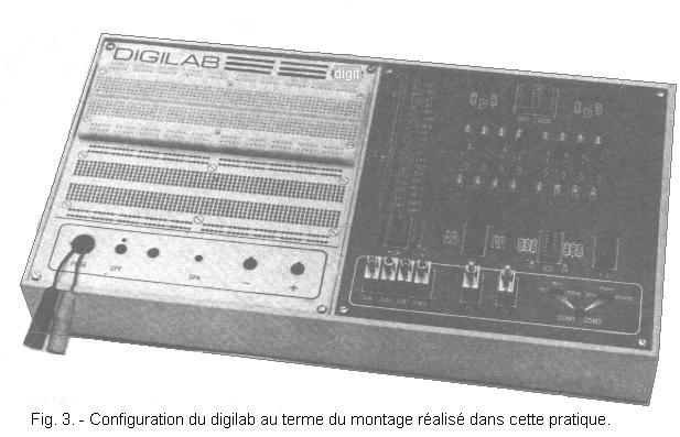
The job is to have on the cabinet the circuit board of the digilab and the front face on which the matrix will be fixed and the self-adhesive label reproducing the connections between the contacts of the matrix. Figure 3 illustrates how the digilab appears after the assembly is complete.
Do the editing by following the instructions below :
a) Unscrew the four screws blocking the temporary legs of the Digilab Printed Circuit Board.
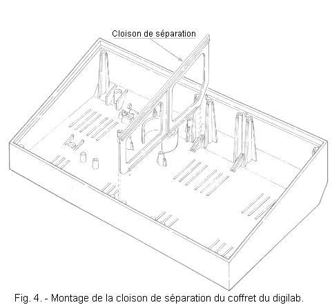
b) Take the cabinet of the digilab and complete it by mounting the partition wall as shown in Figure 4.
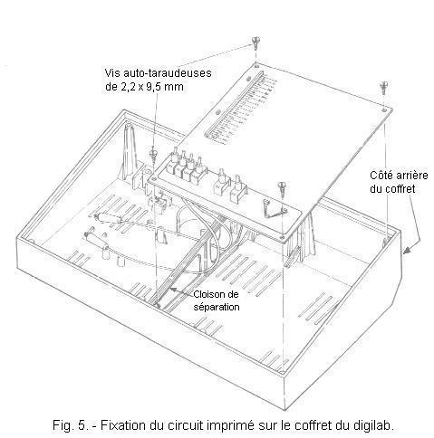
c) Route the two power cords from the printed circuit board through the opening in the partition wall and secure the circuit board to the cabinet in the position shown in Figure 5, using four self-tapping screws of 2.2 x 9.5 mm.
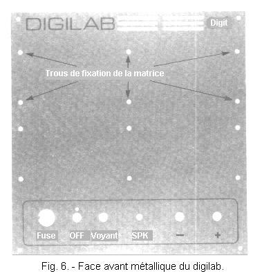
You must now attach the die and self-adhesive label to the metal front of the digilab. The latter, as you can see in Figure 6, is provided with twenty-two holes ; four of them at the corners serve to fix the front face on the cabinet, six serve to fix the matrix, the other six can be used to fix an additional matrix that could be added in case you wish to increase the possibilities later of the digilab.
The location reserved for this second optional matrix will be occupied by the self-adhesive label which represents, as has been said, the internal connections between the contacts of the matrix.
The remaining holes, which are inside the silkscreened rectangle on the lower part of the front panel, will be used in a later practice when the digilab is completed by the power supply.
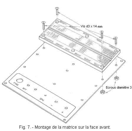
d) Take the matrix, place it on the upper part of the front face, so that the fixing holes of the matrix are in correspondence with those present on the front face. Attach the die to it using the four countersunk Ø3 x 14 mm screws and four Ø3 nuts at the four corners as shown in figure 7.
The two holes in the center of the matrix must remain free for the moment.
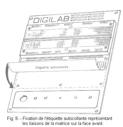
e) Take the self-adhesive label representing the links of the matrix, detach the protective sheet from the adhesive surface and stick it on the front, just below the matrix by positioning it, in correspondence with the six holes in the front panel, just as if it were a second matrix (Figure 8).
In this way, the six holes that would be used to fix a second matrix are covered and at the same time you have the advantage of having constantly under the eyes the connections between the contacts of the matrix. This will be particularly useful in the beginning, as long as you have not yet gained sufficient experience in the use of the contact matrix.
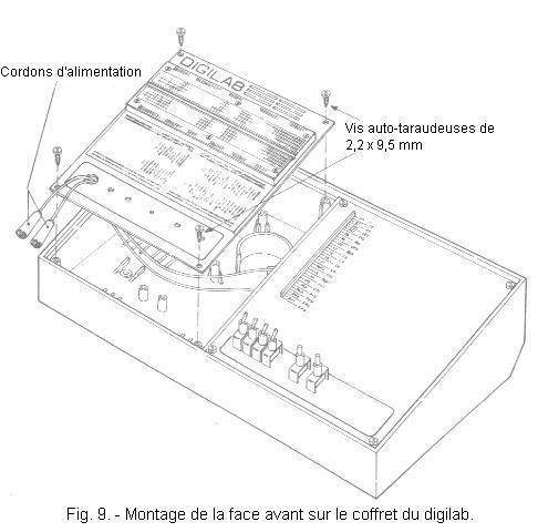
f) Finally, feed the two alligator clips from the circuit board power cords through the larger hole in the front panel (the one at the bottom left), and attach the left end of the cabinet to the left opening of the cabinet using four Self-tapping screws of 2.2 x 9.5 mm as you can see in Figure 9.


 Matrix with contacts
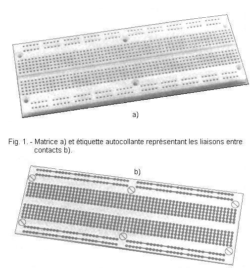

 Click here for the next lesson or in the summary provided for this purpose.
 Top of page
 Next Page