1
integrated circuit MM 74C00 that you had during the previous lesson (2nd practice). You will thus use some pieces of insulated rigid wire already used in the previous experiments and you will prepare new ones by taking them on the braid in your possession.
2. - ASSEMBLY OF THE SWITCH GROUP
To perform this work, observe the following guidelines :
Take a switch and place it on the circuit board so that the notch visible on the cylindrical top is turned away from the SW0 inscription as shown clearly in Figure 1-b.
After making sure that the switch is inserted in its place and keeping it in contact with the board, perform the welding of the 7 terminals.
Using the same method, arrange the other 3 switches at their respective locations marked on the circuit board by the abbreviations SW1, SW2, SW3 and solder the terminals to the corresponding copper pads.
2. 1. - OFF-VOLTAGE CONTROL
Before performing this check, make sure all four switches are oriented as shown in Figure 1-a. Check that the welds are executed correctly.
Then do the following :
Arrange the levers of the four switches so that they are directed towards the 0 symbol on the PCB as shown in Figure 1-a.
Prepare the controller for the Ω x 1 000 resistance measurement. Put one test point on one of the connector group contacts marked with "-" and with the other end touch the SW0 contact of the connector group. The needle on the device must indicate a zero resistance value.
Keeping the test probes on the same contacts, move the switch lever SW0 to symbol 1 ; the needle must indicate in this case an infinite resistance value.
Now move the tip of the contact on the "-" contact and put it on one of the "+" contacts leaving the other point on the contact SW0 ; the device must indicate a zero resistance value.
Keeping the controller touch points on one of the "+" contacts and on the SW0 contact, set switch SW0 to the position indicated by the symbol 0. The pointer will indicate an infinite resistance value.
With these tests, summarized in measurement points 1 and 2 of the table in Figure 2, you have completed the control of the SW0 switch.
In the same way, successively check the switches SW1, SW2, SW3 by carrying out in the order indicated in the table of Figure 2, the measurements between the different points specified in the second column and by arranging the lever of the switch concerned. alternatively on positions 1 or 0 as indicated in the third column.
If one of the control points does not give the result shown in the last column of the table in Figure 2, review the assembly. Check the exact position of the switches, the welds made and make sure there are no cut tracks or short circuits between neighboring tracks.
Once you have obtained the correct measurements for each switch, you will be able to perform the functional test.
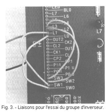
2. 2. - OPERATING TEST
To perform this test, follow the instructions below :
set the levers of the 4 switches to the 0 position.
using 4 pieces of 10 cm insulated rigid wire, connect together the points of the group of connectors shown below and illustrated in Figure 3.
SW0 contact with contact L0
SW1 contact with contact L1
SW2 contact with contact L2
SW3 contact with contact L3
then feed the circuit, connect the red and black cords to the battery ; the four LEDs marked L0, L1, L2 and L3 remain off.
then move the switch levers to position 1 ; in this case, LEDs L0, L1, L2 and L3 light up.
You have now checked the operation of the switch group whose electrical diagram is shown in Figure 4.
The two positions, which can take the common contact of each switch, are marked with the symbol 1 and 0. The symbol 1 is associated with the position making available on the group of connectors a voltage level "high" (+ 4.5 V), while the position represented by the symbol 0 corresponds to a low voltage level (0 V).
You can now carry out the practical experiments, the purpose of which is to give you the opportunity to familiarize yourself with the characteristics of the basic components used in digital circuits.


 Footer
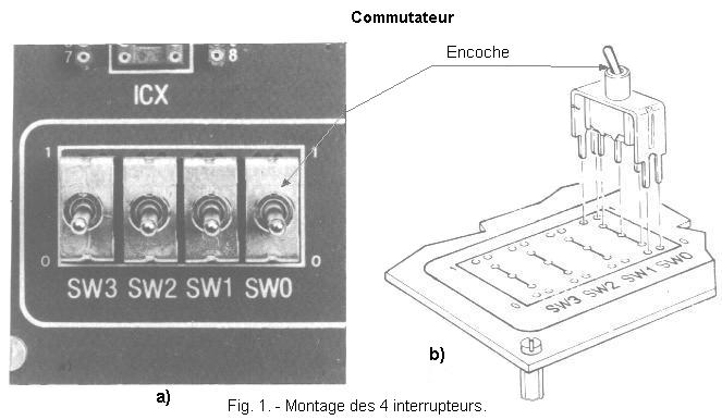
 Click here for the next lesson or in the summary provided for this purpose.
 Top of page
 Next Page