 The subtraction The subtraction |
 The multiplication The multiplication |
 The division The division |
 Footer Footer |
Operations in Digital Machines :
7. - OPERATIONS IN DIGITAL MACHINES
7. 1. - ADDITION IN DIGITAL MACHINES
In Chapter 5. 2., we have seen the principle of binary addition. In digital systems, there is no difference and it is the basic operation.
It is performed from simple cells (logical operators) that constitute the combinational logic circuits.
The table of the binary addition (Figure 14) corresponds to the truth table of the EXCLUSIVE OR operator.
In binary, if one makes the following sum : 1 + 1 = 10
The least significant digit (C.L.M.S.) is a 0 (result corresponding to the cyan portion of Figure 14). The most significant figure (C.L.P.S.), which is the carryover is 1.
C.L.M.S. is given by the output of the exclusive OR circuit, while the carry, or C.L.P.S., is provided by the output of the AND circuit.
The diagram of this adder is given in Figure 31 as well as its truth table. It deals with the addition of two one-bit numbers.
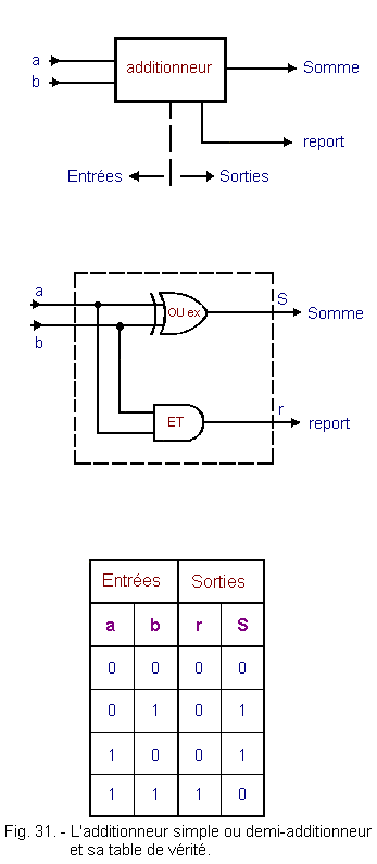
This representation assumes that this adder can not receive any external report, resulting from a previous calculation.
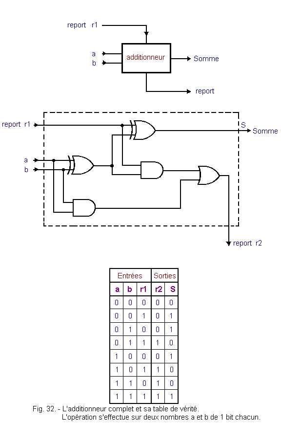
This is rarely the case and to trivialize the circuits, we consider an additional entry corresponding to this report.
The circuit becomes that of Figure 32 with its truth table.
The operation involves two numbers of one bit each.
Numbers with more bits are added in the same way. Each adder will see on its inputs bits of identical weight.
Figure 33 gives the diagram of an adder on two numbers of four bits in pure or natural binary. The first number being formed of the bits a0, a1, a2, a3 and the second number of b0, b1, b2, b3. This is not about signed numbers, multiple precision or floating point numbers.
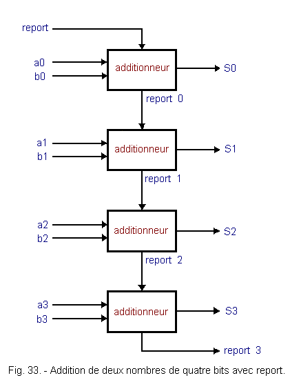
Adders requiring high speed of operation are designed a little differently. They take the name of adders to carry forward as opposed to the one we just described where the carry is serial spread.
On these adders advance carry, it is recalculated for each floor according to the previous bits.
![]() 7. 2. - THE SUBTRACTION
7. 2. - THE SUBTRACTION
We wrote at the beginning of this chapter that it would be interesting to use a universal procedure that would serve all operations. It is a wish that would make things easier. Since we have just described the addition, let's see if these circuits can not be used for subtraction.
We know that the complement to 2 (represented by C2) is used to represent negative numbers.
Performing a subtraction amounts to making an addition whose second term is negative.
In addition, you should know that in digital systems, words all have the same format. This format corresponds to the length of the registers.
Example :
In a system working on eight-bit words, the decimal number (+ 4) is in the form : 0000 0100.
The decimal number (- 9), in the representation of negative numbers by the C2, is in the form : 1111 0111.
The same format means that these numbers use eight bits for their representation. Let's see what happens with an example.
-
Either to subtract (+ 4) of (+ 9).
(+ 9) Þ 0000 1001
- (+ 4) becomes (- 4) Þ 1111 1100
Figure 34 shows this operation.
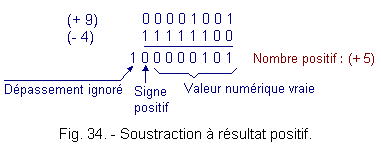
The overflow or overtaking is ignored because it falls outside the storage capacity of the register which has only eight cells (thus eight bits : eight bits).
The most significant bit is a 0, as it indicates the sign of the absolute value, this number is positive and, therefore, the numerical value found corresponds to that of the result.
What happens when the second term is, in absolute value, larger than the first ?
Let subtract (+ 9) of (+ 4), the Figure 35 shows this operation.

The result gives a number having a 1 to B.L.P.S. (most significant bit), so a negative value.
Since we have opted for the representation of numbers by the complement to 2, if the sign is negative, the numerical value that follows can only be the complement to 2 of the number sought.
Let's transform into decimal :
11111011 Þ C2 Þ 00000101 Þ (- 5)10
If this result is to be used for other calculations, it will remain in the machine as a complement to 2.
If this result is the end of a calculation, before sending it to a display in order to visualize it (case of a calculator), it will be necessary to carry out the complement to 2 of the result then to direct this one and the sign to the displays correspondents.
2
and the negative sign (-) are linked to each other.
For example, if we enter, always in the case of a calculator, a first number, it will be stored in binary form.
Before introducing the second number, we indicate the sign of the operation. If it is an addition, the second term will be stored in a second register in the same form as the first one.
If it is a subtraction, inserting the - sign, using the keyboard, starts the complementation procedure.
Once the operation is completed (after pressing the «=» key), if the B.L.P.S. is a 1, the complementation procedure is initiated before sending the result to the display.
Apart from the complementation procedure on the second term or on the result, we use for the subtraction the same adder circuit as that described in figure 32.
The complementation at 2 is obtained from the information contained in the register and on which this complementation must be carried out.
In general, these registers have two outputs, one is the copy of the number previously entered, the other is the complement to 1 of this number (these circuits will be described in a lesson dedicated to them). This second output is directed, if necessary, to an adder. In this, in addition to 1, is added 1 in order to obtain the complement to 2. Figure 36 illustrates this method.
For now, it is only the principles used in digital systems to perform the operations.
These principles are somewhat different from basic arithmetic operations, so it is necessary to clarify them, but it is not yet time to approach the practical realization and the detailed description of the schemas.
The output complement 1 of the register is sent in an adder. In the latter, 1 is added to the complement to 1 to obtain the complement to 2. The next two operations, multiplication and division, are given by way of example, because the practical procedure is sometimes rather complex and several methods are used. However, they are similar to those described below. We know, from chapter 5. 6. that the binary multiplication is a series of additions whose terms are copies of the multiplicand successively shifted. Here again, we find something in common with the two previous operations : addition. In the subtraction, it is necessary to perform, in addition to the addition, the complement to 2. In the multiplication, the additional operation consists of a shift of the partial results before the addition. Example : Let multiply (+ 25)
by (+ 5). We consider that the numbers are represented in the machine by eight-bit words and the negative values by the complement to 2. Figure 37 shows the progress of this multiplication. The B.L.P.S.
is 0, so the number is positive and the numeric value represented by the next seven bits is the absolute value of the result :
1111101
Þ |125| Since the number is positive, the result is :
(+ 125). The part corresponding to the overflow is ignored since the storage register has only eight elementary cells. Let's see what happens if one of the two numbers is negative : Let multiply (+ 25)
by (- 5). Figure 38 shows this new multiplication. Here, the operation was deliberately continued in the overflow part. In practice, this part of the operation can not be done (because of the length of the registers). The
B.L.P.S. is
1, therefore, it is a negative number and such a number is represented by its complement to
2. To find the absolute value of the result, the complementation must be done at 2
(C2). Let :
10000011 Þ C2 Þ
01111101 The absolute value is |125|,
the sign being negative, we find as result : (- 125). With two examples, we notice that the notation, floating point and multiple precision is a necessity because one is quickly limited in the calculations when one works only on words of eight bits or bytes. In summary, for multiplication, starting with B.L.M.S. of the multiplier, each time a 1 is encountered, the multiplicand is copied and shifted by as many ranks towards the strong weights (to the left) as the weight of the multiplier bit.
In practice, we do not perform the multiplication by 0. We thus gain a cycle in the procedure, which results in a slight saving of time. The shift towards the strongest weights is also done in the registers. In fact, instead of a blank, as in the example, each partial result is stored in a register and the contents of it are pushed to the highs by introducing the B.L.M.S. a 0. Registers are very important circuits in electronics. They are part of so-called sequential circuits. On the other hand, the shift towards the strong weights is used, as in decimal, for the multiplication by a power of the base. Example :
in decimal :
in binary : To multiply
0110 by 010. 0102
is an integer power of base 2
(in decimal 0102 = + 2101). Figure 39 shows this multiplication.
In this example, we performed the product with the 0
from the B.L.M.S.
On the other hand, it was not done for the 0
of B.L.P.S.
or sign bit. In addition, the offset here is one rank to the highest since 102 Þ
2101.
The exponent of the power of 2 indicates the offset. We could have taken instead of 102, 10002,
is 2103.
The result is, in this case : 0110 x 01000 = 0110000 The shift here is three ranks to the higher powers. Since it is the most difficult arithmetic operation, the procedure used in the machine does not simplify it. It is good to know the mechanism. However, if the latter is not well assimilated, this does not lead to unfortunate consequences for the continuation of the program. It will always be time to come back to this topic when it suits you.
We use for this operation, the adder, the complement to 2 (addition and complement to 2 = subtraction), the offset, the search for the rank occupied by the highest-order bit a 1 of the divisor, the test of the bit of sign, numeric magnitude comparison and, of course, memorization or storage. We will take our example on the following division : 010101 / 011 These numbers, once stored in the eight-bit registers, are in the following form :
00010101
- dividend 00000011
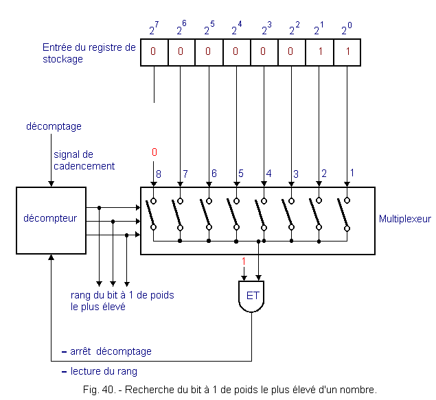
- divider The sign of the operation, or operator, is also stored in a register, specially designed for this purpose, in the form of a binary word. For this operation, there is a preliminary procedure that is triggered by the introduction of this operator and which consists in recognizing the rank occupied by the bit 1 of the highest weight of the absolute value of the divider. This operation can be performed according to the principle illustrated in Figure 40 and that we will describe. It recognizes the storage register that is familiar to us, followed by a multiplexer controlled by a countdown and an operator AND that you know. The multiplexer and the down-counter will be described in detail in the following theories. Know for the moment that the multiplexer is a circuit in which each input is joined to the common output by a switch (bipolar transistor or MOS). The closure of each of these switches is obtained by a binary information present at the input of the multiplexer. This information can only control one switch at a time. The binary information is obtained, in our case, by a down-counter. The countdown rate is obtained by a timing signal applied to an input of the downcounter. This circuit has a second input, connected to the output of the AND operator, which stops the countdown as soon as it goes to logic level 1. The output information of the downcounter is in the form of an n-bit number ; in this case, three bits are enough because we count down from 7th rank to 1st rank (from 1112 to 0012). This number is encoded in natural binary form as shown in Figure 41. As soon as the «stop countdown» input goes to 1, the countdown is stopped, and the reading of the binary information present at the output of the down-counter indicates the rank of the bit at 1 of the highest weight of the absolute value of the divider. The eighth rank, which corresponds to the sign of the absolute value, is not taken into account for the moment. This information is stored in memory and the complementation operation can be performed because the sign memorized in the register of the operator (here the division ; /) involves the search for the complement of 2 of the divider.
Are now present in the machine :
The Dividend
Þ
0001 0101 The divider
Þ
0000 0011 The rank of the bit at 1 of highest weight
Þ
010 The complement to 2 of the divider
Þ
1111 1101 In the decimal division, we seek to find out how many times the divisor is contained entirely in the number formed by as many higher weight digits as the divisor contains. In other words, subtract the divisor from the highest weights of the dividend. We perform this operation mentally, but digital circuits can not do this. This is the reason for this search for the highest 1-bit of the divider. We perform the subtraction by adding the complement to 2 and if the sign bit is a 1, the result is negative, which means that the term subtractor has an absolute value greater than that of the subtracted term. We deduce that the subtractor, in this case, is not contained in the number formed of the strongest weights of the dividend. We are, therefore, obliged in this operation to count with the sign bit. The previous operation which allowed us to know the rank of the bit with 1 of the highest weight, does not take into account the bit of sign. For this purpose, to the binary information present at the output of the down-counter, we must add a rank. The information present in the machine are : The dividend
Þ
0001 0101 The divider
Þ
0000 0011 The rank of the bit at 1 of the highest weight, plus one row for the sign Þ
011 The complement to 2 of the divider
Þ
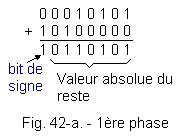
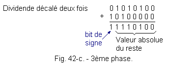
1111 1101 Of course, the sign of the operation also remains in the operator register. From now on, we can start the operation. The disposition of the operation requires an explanation. We searched for the rank containing the most significant divisor, plus a rank for the sign, so that we could subtract the divisor (in our case, add its complement to 2), the highest digits of the dividend, for whether it is contained entirely in the latter. This procedure allows us to shift the complement to 2, to the left, to align it under the same number of ranks, the highest weight of the dividend, that it contains itself. Let's go back to the operation. Figure 42-a shows the first phase of the operation.
a) 1st phase :
It is necessary
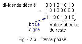
to test the sign bit to know the result of the operation. This is relatively easy to obtain, it is sufficient, as in Figure 40, to use an AND logic operator to which the sign bit is sent on one of its inputs and a 1 on the other. As soon as the sign bit goes to 1the output of the AND operator takes state 1. When this output is in state 1, it means that the divisor is not contained in the number formed by the highest weight figures of the dividend. In this case, as for the decimal division, we will build a new number with a rank number added to the dividend. This amounts to shifting, to the left, the dividend. Since the divisor is not contained in the first strongest terms of the dividend, the first digit, of the highest weight, of the partial quotient is : 0. After this first phase, the partial quotient is in the form : 0 . . . . . . b) 2nd phase : The dividend is shifted one time to the left (Figure 42-b). The sign bit of the remainder is 1, so the result is negative, the divisor is still not contained in the most significant terms. The partial quotient becomes :
0 0 . . . . . New dividend shift. c) 3rd phase : Figure 42-c shows the operation after two offsets to the left of the dividend. Result identical to the first two phases. The sign bit of the remainder is still 1. The new partial quotient is
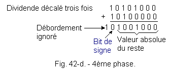
: 0 0 0 . . . . d) 4th phase : After a new shift to the left, the operation is as shown in Figure 42-d. There, the sign bit is 0, which means that the divisor is contained in the highest weight terms of the dividend. The partial quotient becomes :
0 0 0 1 . . . Successive additions will no longer relate to the dividend but on the rest (as in decimal), the shift operation continues on the absolute value of the rest. Before continuing, make sure that the absolute value of the remainder is greater than the absolute value of the complement to 2 of the divider. This comparison circuit is described a little further. So if the absolute numerical value of the remainder is greater than that of the C2
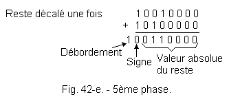
of the divider, the operation continues. e) 5th phase : The operation then continues with, as a new dividend, the previous rest shifted once to the left (Figure 42-e). The sign bit is 0,
hence the new partial quotien : 0 0 0 1 1 . . Offset to the left, the absolute value of the rest. Comparison of digital quantities. The rest is larger than the C2
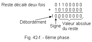
of the divider, the operation continues. f) 6th phase : The operation continues with the rest shifted twice to the left (Figure 42-f). The sign bit is 0,
the new quotient has the value : 0 0 0 1 1 1 . Shift to the left, the absolute value of the rest and comparison of numerical values. The absolute value of the shifted remainder is smaller than the complement of 2 of the divider, the operation stops. Here, the absolute value of the remainder is equal to 0, the quotient is exact and the last bit obtained at the partial quotient constitutes the B.L.M.S. quotient (lowest weight). In the quotient storage register, the result is in the following form :
0000 0111. In the last comparison between the absolute values of the rest and the
C2
of the divisor, we had a lower result for the rest and equal to
0. This result could have been lower, but not equal to
0, and in this case the division stops, but has a remainder. The quotient is then an approximate quotient. Fractional number division is also possible, but floating-point notation is preferable and facilitates the procedure for the decimal point position. The division is then carried out on the mantissas and the value of the exponent is found by subtracting that of the divisor from that of the dividend. In decimal, this returns to the following example : Or to divide
0,125 by
3 :
0,125 = 0,125
x 100 3
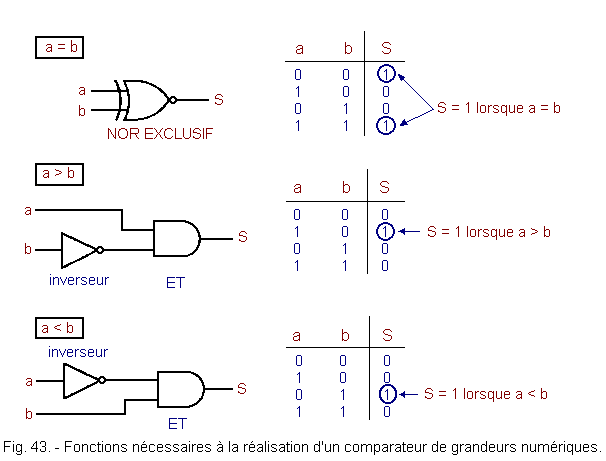
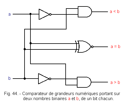
= 0,3 x 101 Division performed on the mantissas: : (+ 125) / (+ 3) =(+ 42) Difference of exhibitors : (0) - (+ 1) = (- 1) Floating point result : (+ 42) (- 1) Transformation to decimal : (+ 42) (- 1) = 0,42 x 10-1 = 0,042 The principle just described recalls the main lines of division performed in a digital system, because the smallest details, recorded in writing or made mentally, are sometimes the subject of a complex assembly of circuits for their elaboration. In addition, the manufacturers of calculating machines and, in general, those who have to make such circuits, whether wired or micro-programmed logic, use their own methods, but that they rarely disclose. In any case, the basic operator remains the adder. The procedures necessary for the proper conduct of the result for the operations described are : memorization addition complementation to 2 looking for the rank occupied by the highest 1 bit of a number the sign bit test the comparison of numerical quantities. The test of the sign bit, using the AND operator, allows us, by inverting (that is to say taking the complement to 1), the result available at the operator's output, to extract the absolute value of the quotient. It is therefore the inverted output of the AND operator that will be used to load the absolute value of the quotient into the register intended for this purpose. During these descriptions, we spoke of ignored overflow. In fact, this overflow is not always ignored, it is even sometimes stored in a register and serves, among other things, to indicate an overflow. In microprocessors, a special register called a status register, contains a number of indications of this kind that can be tested at any time to give a different orientation to the following procedures when needed. Figure 43 represents the logic functions necessary for producing a comparator of digital quantities. This is summarized in Figure 44 which shows a numerical magnitudes comparator on two binary numbers a and b of one bit each. At the beginning of this chapter, we wanted only one procedure for all operations. Now that we know the problem better, let's see if we can get this procedure, in the case of a very simplified calculator, which could only perform additions and subtractions on relative integers. Let's make a list of the different operations that this machine will have to perform.
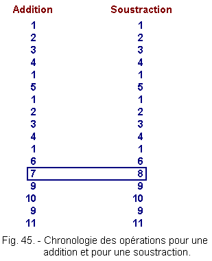
The chronology of the operations is thus that represented Figure 45. It appears more clearly that only the operations If one wanted to extend the possibilities of this machine to the multiplication and division, it would be necessary to introduce the offset, the numeric magnitude test and to look for the rank of the bit with 1 of the highest weight. The list of operations would be a little longer, but the speed with which they are carried out would differ only a very short time from obtaining the result. This theory is now complete. We remind you that if you have not fully assimilated the calculation part, this is not of fundamental importance for understanding the following lessons. We will have the opportunity to return to it in theories concerning microprocessors. The next lesson will deal with shift registers, the role of which has already been discussed in this theory.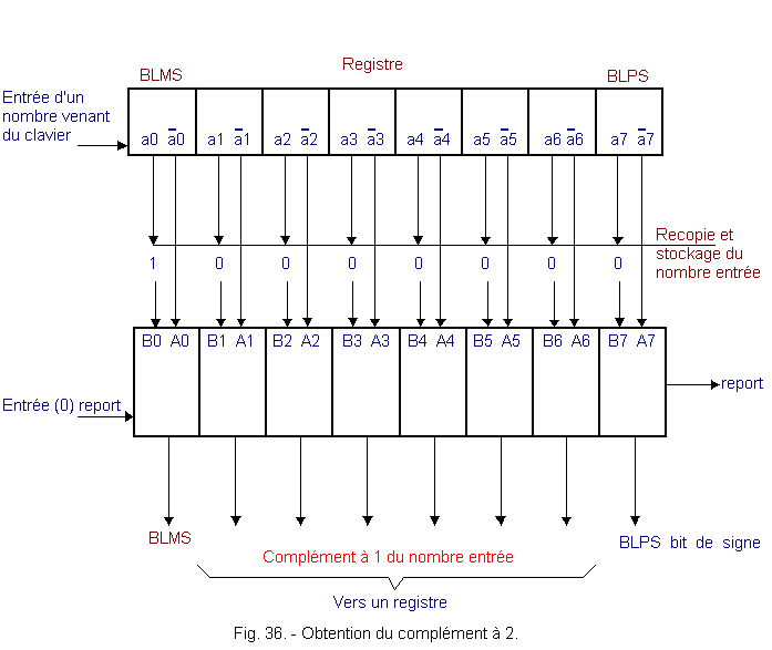
![]() 7. 3. - THE MULTIPLICATION
7. 3. - THE MULTIPLICATION_par_(+5)_en_binaire.gif)
.gif)
.gif)
.gif)
.gif)
![]() 7. 4. - THE DIVISION
7. 4. - THE DIVISION



![]() Information waiting position or input keyboard scan.
Information waiting position or input keyboard scan.![]() Enter the absolute value of a decimal number using the keyboard :
Enter the absolute value of a decimal number using the keyboard :![]() Transformation of this value into binary and stored.
Transformation of this value into binary and stored.![]() Input of the sign assigned to this absolute value :
Input of the sign assigned to this absolute value :![]() Sign +, set the sign bit to 0
Sign +, set the sign bit to 0![]() Sign
-, make the complement to 2.
Sign
-, make the complement to 2.![]() Save the signed number obtained in
Save the signed number obtained in ![]() and
and ![]() .
.![]() Entry of an operator sign by the keyboard. Remember this sign.
Entry of an operator sign by the keyboard. Remember this sign.![]() Enter the sign «=».
Departure of the operation.
Enter the sign «=».
Departure of the operation.![]() The recognized sign in
The recognized sign in ![]() is that of the addition :
is that of the addition :![]() Add the stored terms to
Add the stored terms to ![]() .
.![]() The recognized sign in
The recognized sign in ![]() is that of the subtraction :
is that of the subtraction :![]() Perform the complement to 2
of the last number entered and add this complement to the first term entered.
Perform the complement to 2
of the last number entered and add this complement to the first term entered.![]() Save this result.
Save this result.![]() Perform the test of the sign bit :
Perform the test of the sign bit :![]() If it is equal to 0, the result is positive, no modification on the result stored in
If it is equal to 0, the result is positive, no modification on the result stored in ![]() .
.![]() If it is equal to 1, the result is negative, replace the term stored in
If it is equal to 1, the result is negative, replace the term stored in ![]() by its complement to 2.
by its complement to 2.![]() Display the stored result in
Display the stored result in ![]() .
.
![]() and
and ![]() are somewhat different between the addition and the subtraction. It is an addition but for
are somewhat different between the addition and the subtraction. It is an addition but for ![]() one of the two terms is complemented with 2.
one of the two terms is complemented with 2.
 Click here for the next lesson or in the summary provided for this purpose.
 Top of page
 Previous Page
 Next Page
Nombre de pages vues, à partir de cette date : le 27 Décembre 2019
Envoyez un courrier électronique à Administrateur Web Société pour toute question ou remarque concernant ce site Web.
Version du site : 10. 4. 12 - Site optimisation 1280 x 1024 pixels - Faculté de Nanterre - Dernière modification : 02 Septembre 2016.
Ce site Web a été Créé le, 14 Mars 1999 et ayant Rénové, en Septembre 2016.
