 Footer Footer |
Introduction to Sequential Systems :
In this theory, we will examine the sequential systems that are the basis of the circuits used in automation and computers.
1. - INTRODUCTION TO SEQUENTIAL SYSTEMS
1. 1. - SEQUENTIAL SYSTEMS
The logical circuits examined so far have the property of providing at output and at a given instant, logical values which depend solely on the combination of the logical values applied at the same time to the inputs (naturally neglecting the delays due to spread).
For this reason, these circuits are called combinatorial because their output state is a function of the combination of logical states applied to their inputs.
In addition to the circuits seen previously, there are others that have the ability to memorize the signals. Their output is then a function not only of the instantaneous combination of the input signals, but also, because of their memory property, combinations of the logic signals previously applied to their inputs.
Those circuits in which the output depends on the previous logic states of the inputs are commonly referred to as sequential circuits.
1. 2. - SYNCHRONOUS SYSTEMS
A sequential system is said to be synchronous when the change of state of the outputs is controlled in time or synchronized. It can be by the inputs themselves or by a single signal common to all editing. This particular signal is called clock. We will come back later to the notion of clock.
1. 3. - ASYNCHRONOUS SYSTEMS
A system is said to be asynchronous when the state change of the outputs is not controlled by any particular input, unlike a synchronous circuit.
1. 4. - TIMING CONCEPTS OR CHRONOGRAM
In order to obtain a representation of the evolution of the signals generated by a system and to compare them, graphs are used in which the horizontal axis or x-axis is graduated as a function of time expressed in milliseconds (thousandths of a second) or in microseconds (millionths of a second) for example.
The vertical axis or y-axis is graduated into voltage levels varying between the high level and the low level (H and L).
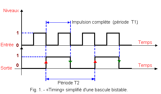
Figure 1 shows the simplified «timing» of a bistable flip-flop that will be discussed later.
The signals obtained in this figure being regular and periodic, it is possible to define for each signal the period (or time) separating two successive pulses.

1. 5. - LEVELS AND FRONTS
The notion of levels is now familiar to us, we know two types : the low level and the high level which are materialized by segments of horizontal lines on the chronogram.
We will call front, the passage from one level to another ; it will be materialized on the chronogram by a segment of vertical line or at least very inclined, because in reality the time of passage from one level to another is not zero and may vary, depending on the systems, some tens of milliseconds to a few tenths of nanoseconds(1 nanosecond = 10-9 seconds).
There are rising fronts, red arrow of the "timing" of Figure 1, and descending fronts green arrow on the same figure.
1. 6. - STATES ASSOCIATED WITH THE NOTION OF MEMORY
1. 6. 1. - RELAY OR MEMORY
Although this device is hardly used in modern systems given its consumption, high response time and prohibitive size, it has the advantage of being simple. In addition, its mechanical operation is easily visible hence its educational value.
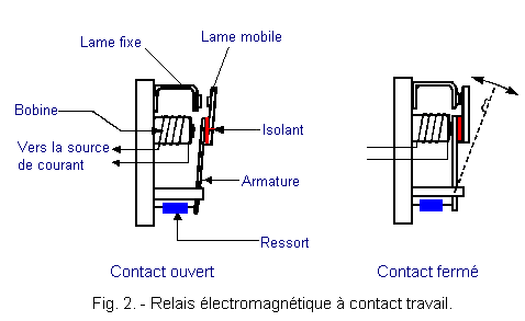
A relay consists of a metal frame and an electromagnet as shown in Figure 2.

When the coil of this electromagnet is energized, the armature is attracted and comes by means of a ladder or isolating wedge to close working contacts or to open rest contacts (in Figure 2, a work contact).
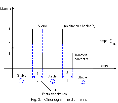
The displacement of the armature is not instantaneous, so closing or opening of a contact is made with a certain delay q with respect to the establishment of the current I traversing the coil (Figure 3).

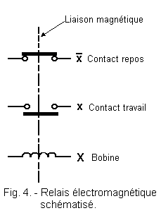
This system allows a back-coupling : the coil of the relay commonly called X (upper case indicating that it is an output variable) is an output variable generating a new bound input variable : x, constituted by one contacts of this same relay.
The graphical representation of a relay adopted in this lesson is that of Figure 4.

1. 6. 2. - STABLE STATES
Stable states are states in which the coil of an X relay, or excitation, is in the same state as its contact x, or transfer.
By convention, the number indicating a stable state is always surrounded by a circle.
Example : X
= 0 x = 0
steady state rest ![]()
X = 1
x = 1 steady state work ![]()
1. 6. 3. - TRANSITIONAL OR UNSTABLE STATES
In the two previous states, there was identity between excitation and transfer. However, the delay of x conditions intermediate or transient states for which excitation and transfer are in complementary states.
Example :
Transitional state 2 (by convention do not circle the number), we have :
X = 1 and x = 0.
The transfer is not instantaneous.
Transient state 1 : we have X = 0 and x = 1
Note :
For a transient state, the transfer is late on excitation.
Rule :
a) For a stable state, the relay coil and its transfer contact are in the same state.
b) For a transient state, the transfer contact keeps in memory the state it had in the stable state preceding the transition.
The relay coil takes the binary value of the steady state to which the transient state is changing.
 Click here for the next lesson or in the summary provided for this purpose. Click here for the next lesson or in the summary provided for this purpose. |
|
 Previous Page Previous Page |
 Next Page Next Page |
Nombre de pages vues, à partir de cette date : le 27 Décembre 2019
Envoyez un courrier électronique à Administrateur Web Société pour toute question ou remarque concernant ce site Web.
Version du site : 10. 4. 12 - Site optimisation 1280 x 1024 pixels - Faculté de Nanterre - Dernière modification : 02 Septembre 2016.
Ce site Web a été Créé le, 14 Mars 1999 et ayant Rénové, en Septembre 2016.
