 Problem N° 2 Problem N° 2
|
Footer |
Resolved Problems - Problem Solution :
6. - SOLVED PROBLEMS
6. 1. - PROBLEM N° 1
![]() Three pieces of equipment : a, b, c, work together. If at least two of these devices fail, it is desired to automatically supply an emergency element X.
Three pieces of equipment : a, b, c, work together. If at least two of these devices fail, it is desired to automatically supply an emergency element X.
* The logic level "1" will indicate the correct operation,
* The logic level "0" will indicate the malfunction.
![]() Give the truth table,
Give the truth table,
![]() Draw the chart of Karnaugh,
Draw the chart of Karnaugh,
![]() After groupings, give the minimum equation,
After groupings, give the minimum equation,
![]() Draw the logic diagram,
Draw the logic diagram,
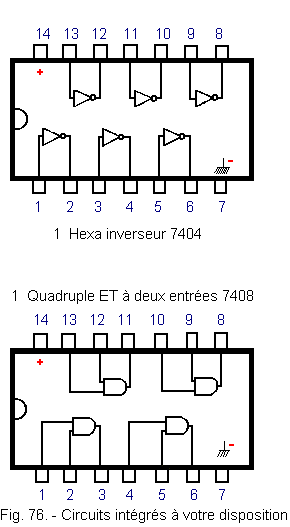
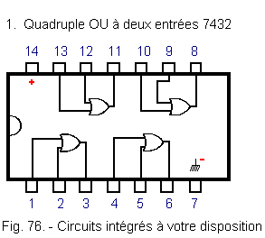
![]() Make this diagram with the inverting integrated circuits, AND, OR ... you have (Figure 76),
Make this diagram with the inverting integrated circuits, AND, OR ... you have (Figure 76),
![]() Indicate on the diagram the pinout of the integrated circuits,
Indicate on the diagram the pinout of the integrated circuits,
![]() Perform the same editing using only NAND functions.
Perform the same editing using only NAND functions.
You have the three circuits shown in Figure 76.
6. 2. - PROBLEM SOLUTION N° 1
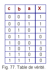
We see that X must be at 1 each time at least two elements on a, b, c are at 0, hence the truth table in Figure 77.
Let us report in Karnaugh's table of figure 78 the levels 1 of X for the corresponding states of a, b and c.
.gif)
According to Karnaugh's table, we can write :
red Grouping = ![]()
![]()
Green grouping = ![]()
![]()
Blue grouping = ![]()
![]()
From where we draw the expression :
X = ![]()
![]() +
+ ![]()
![]() +
+ ![]()
![]()
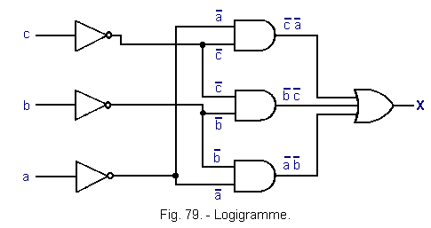
We can now build the logic diagram or logic diagram of Figure 79.
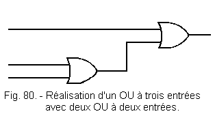
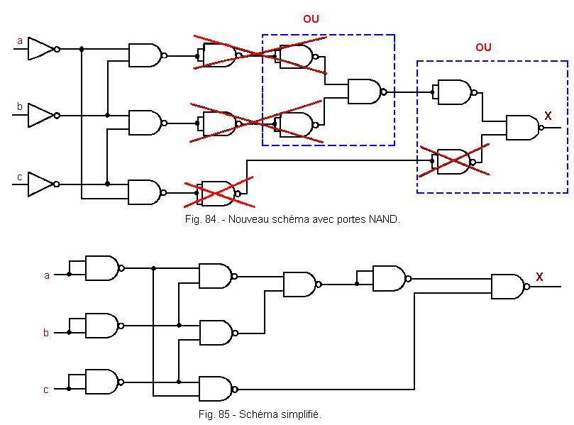
We see that in practice a "OR" with three inputs can be replaced by two "OR" with two inputs (Figure 80).
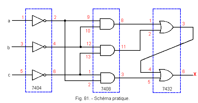
The diagram then becomes that of Figure 81.
Let's replace each logical function with the equivalents from NAND.
According to DE MORGAN's theorem, one can replace one OR by three NAND (Figure 82).
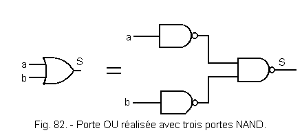
Indeed, ![]() =
= ![]() .
.![]()
From where S = a
+ b = ![]()
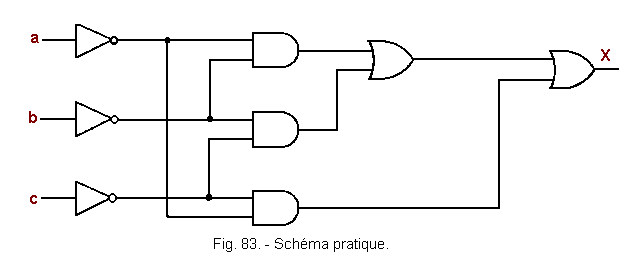
It is therefore possible to transform the diagram of Figure 83 so that it becomes that of Figure 84 and by removing unnecessary inverters that of Figure 85.
![]() 6. 3. - PROBLEM N° 2
6. 3. - PROBLEM N° 2
Consider the device of Figure 86.
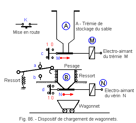
Operation :
![]() On / Off button K is available
On / Off button K is available
![]() Electromagnet "M" can only be energized when contact "d" = 1 (closed valve),
Electromagnet "M" can only be energized when contact "d" = 1 (closed valve),
![]() "c" is then released and becomes
"c" = 0,
"c" is then released and becomes
"c" = 0,
![]() Sand pours into the weighing device B
(a is then at
1),
Sand pours into the weighing device B
(a is then at
1),
![]() Weighing spring crashes, "a"
go to 0, but
"b"
still remains to 0 (intermediate state between "a" and
"b"),
Weighing spring crashes, "a"
go to 0, but
"b"
still remains to 0 (intermediate state between "a" and
"b"),
![]() "b" = 1, this causes the de-excitation of the electromagnet M,
"b" = 1, this causes the de-excitation of the electromagnet M,
![]() The contact "c"
back to 1,
The contact "c"
back to 1,
![]() "c" then excites the electromagnet N and so
"d"
go to 0,
"c" then excites the electromagnet N and so
"d"
go to 0,
![]() The sand pours into the wagon,
"b" = 0,
but "a" still remains to 0,
The sand pours into the wagon,
"b" = 0,
but "a" still remains to 0,
![]() "a" = 1, the electromagnet
N is de-energized, the valve closes,
"a" = 1, the electromagnet
N is de-energized, the valve closes,
![]() The contact
d is then activated, "d" = 1 and the cycle starts again (M is excited,
c
is released ...).
The contact
d is then activated, "d" = 1 and the cycle starts again (M is excited,
c
is released ...).
1°) - Give the truth table of the system for relays M and N,
2°) - Draw up Karnaugh's tables for M and N,
3°) - flowcharts.
6. 4. - SOLUTION OF THE PROBLEM N° 2
6. 4. 1. - TABLE OF TRUTH FOR OUTPUTS M AND N (FIGURE 87)
We will examine the combinations of variables in the order of the process, we will not take into account the unused combinations.
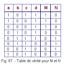
The equations taken from the truth table are :
M equation
M = a![]() cd
+ a
cd
+ a![]()
![]() d
+
d
+ ![]()
![]()
![]() d
d
Equation of N
N = ![]() bcd
+
bcd
+ ![]() bc
bc![]() +
+ ![]()
![]() c
c![]()
The M and N functions are incompletely defined (some combinations of the variables are not used), we consider them at 0 in the Karnaugh table.
6. 4. 2. - KARNAUGH TABLE FOR OUTPUT M (FIGURE 88)
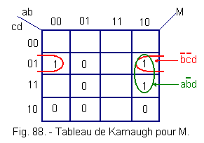
Two groups can be made :
Grouping red = ![]()
![]() d
d
grouping Green = a![]() d
d
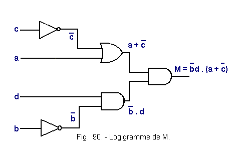
The simplified equation is M
= a![]() d
+
d
+ ![]()
![]() d
d
which can be written : M = ![]() d
(a +
d
(a + ![]() )
)
6. 4. 3. - KARNAUGH TABLE FOR THE OUTPUT N (FIGURE 89)
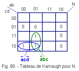
Two groups can be made :
grouping Blue = ![]() c
c![]()
grouping Green = ![]() bc
bc
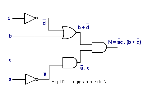
The simplified equation is
N = ![]() c
c![]() +
+ ![]() bc
bc
which can be written : N = ![]() c
(b +
c
(b + ![]() )
)
6.4.4. - LOGIGRAM FOR M (FIGURE 90).
6.4.5. - LOGIGRAM FOR N (FIGURE 91).
The examination of the combinatorial logic is now complete, we will see later the sequential logic, which will allow us to go further in the electronic circuits by making many practical experiments.
The last problem that has been proposed to you is besides at the limit of the sequential because we see for the first time an order of closing of very precise contacts but this problem can still be solved by the methods that we know.
This third theoretical lesson now ends, we advise you to carry out the tests that follow (on a site provided for this purpose) to review a little the concepts that we have exposed so far.
 Click here for the next lesson or in the summary provided for this purpose. Click here for the next lesson or in the summary provided for this purpose. |
 Top of page Top of page |
|
Previous Page |
 Next Page Next Page |
Nombre de pages vues, à partir de cette date : le 27 Décembre 2019

Envoyez un courrier électronique à Administrateur Web Société pour toute question ou remarque concernant ce site Web.
Version du site : 10. 4. 12 - Site optimisation 1280 x 1024 pixels - Faculté de Nanterre - Dernière modification : 02 Septembre 2016.
Ce site Web a été Créé le, 14 Mars 1999 et ayant Rénové, en Septembre 2016.