Information in Digital Systems :
1. - INFORMATION IN DIGITAL SYSTEMS
1. 1. - CONCEPT OF SIGNAL
The signal is the medium of the information. This information carries in itself a message.
Suppose I say :
"The mouse eats the cheese in the pantry."
We can say that I emitted a sound signal. This signal, you've heard it, but you still need to know the language in which I speak, French : in order to be able to decode the information it contains. When you have decoded this information, a message will appear to you.
The message contained in the information is the active component of the signal, it will trigger a reaction on your part : set a trap or repair the fence of the pantry following the logical consequences that you will have drawn from the information.
1. 2. - THE ELECTRONIC SIGNAL
In the previous example, the signal was the acoustic vibration emitted by the voice.
In electronics, signals are also used to carry information : they are electrical signals, that is to say electrical variations.
Suppose now that I want to carry a sound on electrical wires, amplify it, then broadcast that sound in a room (Figure 1).
What systems will we need to implement ?
First, I need a microphone (1) that will transform the acoustic vibration into electrical variation, then a black box (2) that will increase the amplitude of this signal, finally a speaker (3) that will retransform the variation magnified electric, in acoustic vibration, so as to restore the sound.

In a general way, we can say that the microphone and the speaker are transducers : term which designates all the devices transforming a physical quantity in electric variation or realizing the opposite operation.
It is of great interest that the electrical signal is the most accurate image possible of the vibration that gave birth to it, which requires that the microphone is as faithful as possible. In the same way, the loudspeaker must reproduce as faithfully as possible the acoustic image of the electrical signal.
Some of the input transducers include :
![]() the microphones
the microphones
![]() the cameras
the cameras
![]() magnetic heads for tape reading
magnetic heads for tape reading
![]() photoelectric readers
photoelectric readers
![]() temperature sensors
temperature sensors
![]() the strain gauges, etc.
the strain gauges, etc.
Among the output transducers :
![]() the speakers
the speakers
![]() cathode ray tubes.
cathode ray tubes.
The transducers, whether input or output, have the task of transposing the nature of the signal but not to transform the information contained therein.
Inside the black box, we saw that the signal was amplified : we can say as a general rule that we subjected a treatment to this signal. Indeed, to treat a signal, it means : to amplify it, to attenuate it, etc ...
The black box (2) may contain either an analog system or a digital system.
1. 3. - ANALOG SYSTEM
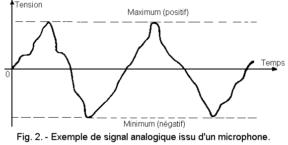
An analog system is characterized in that the electrical signal that it uses has an amplitude or a frequency which is at any time proportional to the physical quantity that it represents. There is an analogy in the evolution of the two quantities over time (example figure 2).
1. 4. - DIGITAL SYSTEM
The digital technique as its name suggests uses numbers.
In a digital system, there is no longer a direct and permanent relationship between the starting physical quantity and the representative electrical variation as to its shape.
The digital signal is materialized by successive voltage levels which can have only two different values, and which represent the digits 1 and 0, the only digits used in a base-based numbering system 2. This electrical signal, consisting of 1 and 0 represents the sequence of values that the physical quantity can take successively. These values are expressed by successive binary numbers.
In electronic circuits, the digital signal is characterized by the presence of voltage or absence of voltage (Figure 3).
These are the two levels that interest us. The transition from one level to another must be carried out as quickly as possible because it is considered a parasitic state.
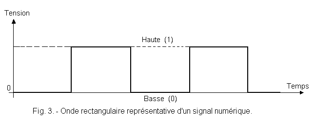
In addition, these two levels will have to be very distinct, so that there is no doubt about the value of the level. One of the important features of the digital technique is that the signal used does not leave room for ambiguity.
1. 4. 1. - THE DIGITAL PRINCIPLE
Why a digital system ? What are the advantages of this system compared to conventional ones, which we call analogical and which have been perfectly mastered for a long time ?
Let's take an example :
A map of geography is the representation on a certain scale of the physical reality of the terrain. At any place, the distances reported are proportional to the actual distances. However, the distances measured on the map depend on the accuracy of the plot.
Given the scale, we multiply the measurement error that is made on the map. We have an analog representation.
If, for example, we measure in centimeters the distance Dijon - the Rochelle, from the number found and the ratio of reduction or scale, we can easily find the real distance. In addition, following the road from Dijon to the Rochelle, it would be possible at each milestone crossed, to note the distance traveled. A simple addition would then make it possible to find this value directly.
In the first method, the figure obtained is a function of the precision of the map and the care taken in the measurement. By cons, using the milestones, the exact result is obtained with a small error that, regardless of the distance measured, can differ only from a terminal in plus or minus.
Analog systems use electrical signals that can be distorted during processing and transport, which will be detrimental to faithful reproduction by the final transducer.
Digital systems only handle numbers that are constants. As long as these numbers are preserved intact, they are characterized by their extreme precision. This precision is known to 1 chiffre or 1 digit (digit = chiffre in English).
Are pocket calculators, quartz watches and other computers not known for their accuracy, and have they not already invaded our modern world ?
In general, it can be said that digital circuits, used in electronics, have many advantages over analog circuits :
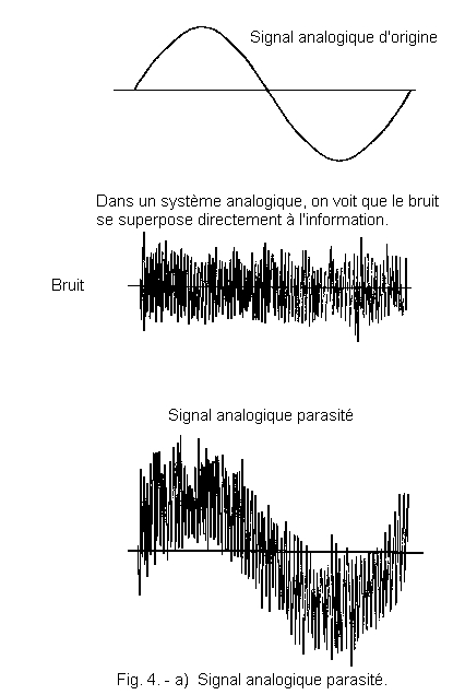
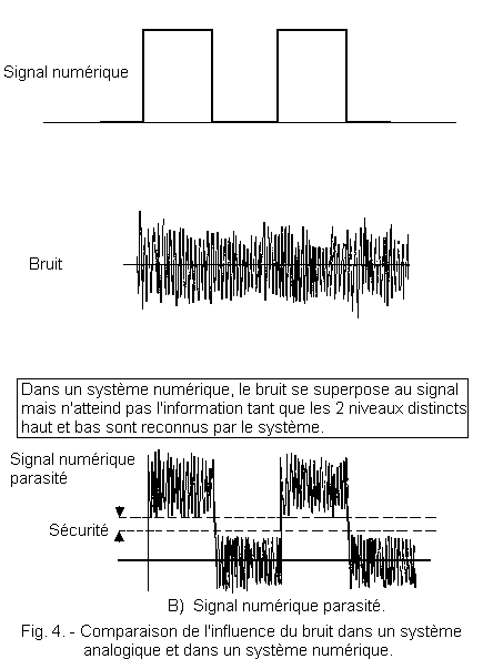
![]() They are not very sensitive to disturbances, since parasitic variations in their amplitude are not taken into account because they are not significant (Figure 4).
They are not very sensitive to disturbances, since parasitic variations in their amplitude are not taken into account because they are not significant (Figure 4).
![]() They do not require long and tedious adjustments, which reduces their cost price.
They do not require long and tedious adjustments, which reduces their cost price.
However, they also use input and output transducers whose fidelity is a condition of the quality of the system.
It is necessary, in input, in addition to the physical / electrical conversion carried out by the transducer, to follow this one of a circuit which converts the obtained analog electrical signal into a digital signal. This circuit is called analog / digital converter (A / D). The circuit performing the inverse operation, at the output, is called digital / analog converter (D / A).
1. 4. 2. - ANALOG / DIGITAL AND DIGITAL / ANALOG CONVERSION
To convert analog signals into digital signals is to transpose the signal code, without modifying the information they contain. Which means, of course, that a signal that has undergone two successive inverse conversions will return exactly to its original form.
The analog / digital conversion (A / N) still called P.C.M. (Pulses Code Modulation) or in French M. I. C. (Modulation par Impulsions Codés) is illustrated in Figure 5.
The analog wave (a) is sampled (b), that is to say measured at regular intervals sufficiently close together. The sampling frequency is very large compared to that of the analog signal and particularly with respect to the highest frequency component in the case of composite signals.
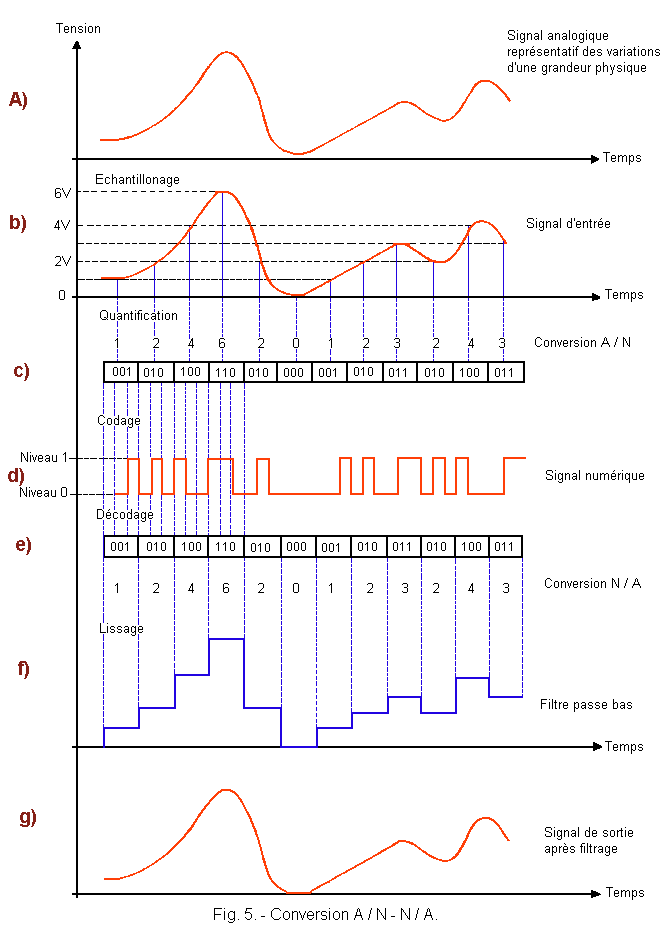
The values thus measured are then translated into a number coded in binary (c), which is in the form of a succession of pulses (d). The digital signal thus formed can then be used in the digital system (computer, radio transmitter, magnetic tape, hi-fi system, etc.).
At the end of the chain, the pulse train is detected and returned in binary form (e). By means of a digital / analogue (D / A) converter, the analog wave (f) is reconstructed.
The angular signal passes through a low-pass filter (g) to return to its original shape.
A low-pass filter is a device well known in analog electronics. This, as the name suggests, only allows low frequencies.
This system has the effect of removing the steep edges of the signal from the D / A converter to keep only the envelope of the lower frequency signal, and thus reconstruct the original form of the analog signal by smoothing.
1. 4. 3. - THE CODING
We have seen previously that the digital signal was composed of a sequence of pulses of level 1 or 0. These pulses 1 or 0, functions of the successive values that takes the physical quantity that they represent, can be coded in various ways.
![]() Binary code
Binary code
You are accustomed to counting in a 10-based numbering system in which there are 10 signs : 0, 1, 2, 3, 4, 5, 6, 7, 8, 9.
The binary system is a 2-based numeration system, that is to say a system in which only 2 signs : 0 and 1 are used.
Other codes are also used, they are non-natural forms or derived from the binary number. They make it possible to avoid errors in case of loss of a bit (contraction of the English binary digit : chiffre binaire) or to reconstitute the lost information : they add to the security of the digital system.
All these codes will be studied later.
1. 4. 4. - DIGITAL ANALOGUE MIXED CIRCUITS
For those who do not have much professional experience, it is difficult to physically distinguish the technique used for the design of a device.
For an integrated circuit, if one does not know its destination, the distinction is practically impossible.
It can now be understood that a circuit must be constructed to accept one of two types of digital or analog signals. It will only interpret the signals of the technique for which it was designed. It may happen that a device uses both forms of signals, but in this case the analog signals are distributed to the analog circuits, and the digital signals to the corresponding circuits.
On the other hand, it may be that a signal comes in analog form in a circuit and comes out in digital form or vice versa and this thanks to the converters we talked about.
![]() 2.
- EXAMPLE OF PROBLEM RESOLVED BY ANALOGUE TECHNIQUE THEN DIGITAL TECHNOLOGY
2.
- EXAMPLE OF PROBLEM RESOLVED BY ANALOGUE TECHNIQUE THEN DIGITAL TECHNOLOGY
Before going to the study of the basic functions and the algebra of Boole, we will make the comparison between two elementary montages, one analog, the other digital.
However, it should be noted, as a warning, that this example has been deliberately very simplified and reflects only very distantly what would be done in the technical reality; but it allows an approach to this comparison. It must be known that for a given problem, there are two techniques to solve it: one analog, the other digital, but the physical quantities at the entrance and exit of the two systems are identical.
That being said, let's pose the elements of the problem to be solved in these two techniques :
![]() You have a work table that is located near a window, so you get the illumination due to sunlight. The work you do on this table requires significant and constant lighting. This natural light can not be given to you all day long, either because the sun is hidden by clouds, or because it is no longer present (when it is dark).
You have a work table that is located near a window, so you get the illumination due to sunlight. The work you do on this table requires significant and constant lighting. This natural light can not be given to you all day long, either because the sun is hidden by clouds, or because it is no longer present (when it is dark).
You will need to have additional lighting, which is nothing but a desk lamp.
But you're a technician, and you're not just pressing the switch to turn your lamp on or off. You decide to make this system automatic.
You know that there are two techniques in electronics to solve your problem, to extend your personal experience, you plan to make 2 montages, one using the analog technique, the other digital technique.
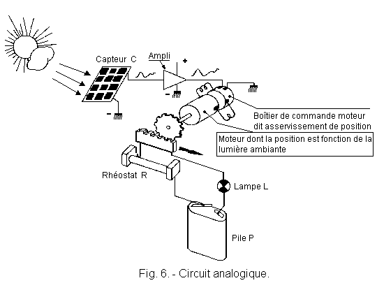
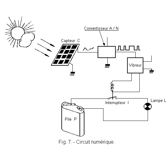
Figure 6 represents the circuit diagram using an analog signal, Figure 7 also represents the diagram corresponding to a digital signal.
We find in both cases, a common starting point, the sensor (c) or transducer that can translate the physical quantity corresponding to sunlight into an analog electrical signal, image of this light.
The second common point is of course the lamp and its power circuit.
The signal from the transducer will inform your system on the value of solar illumination and it will perform the necessary maneuver to light more or less the lamp. Thus, over time, the luminous flux on your table will remain virtually constant.
Except for these two points in common, the procedure is quite different in one or the other case.
![]() Analog Mounting (Figure 6)
Analog Mounting (Figure 6)
The sensor (c) provides a signal proportional to the illumination it receives (Figure 8 shows the variation of the light, during the day). This electrical signal is amplified and then applied to a small motor for moving the slider of a rheostat.
This rheostat is, in fact, a variable resistor. The installation of this system will be done in such a way that any increase in the sunlight corresponds to an increase in the resistance value of the rheostat.
In doing so, when the external light increases, the luminous intensity of the lamp (L) decreases (curve of Figure 9). Between the extreme positions, with the lamp on and the lamp off, there is an infinity of illumination values (in theory).
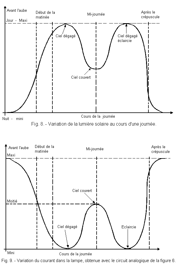
In this figure, it is considered that the luminous flux emitted by the lamp is proportional to the current flowing through it. Figure 9 is the inverse curve of Figure 8. The curve of Figure 9 corresponds to the complement of curve 8. It represents the value of illumination which must be added to the natural illumination in order to obtain the desired result.
![]() Digital editing (Figure 7)
Digital editing (Figure 7)
Referring to Figure 7, the sensor is followed by an analog / digital converter which will take samples from the curve of Figure 8 and assign them a numerical value or quantify them (an operation which consists in assigning each sample a numeric value that is to say a number).
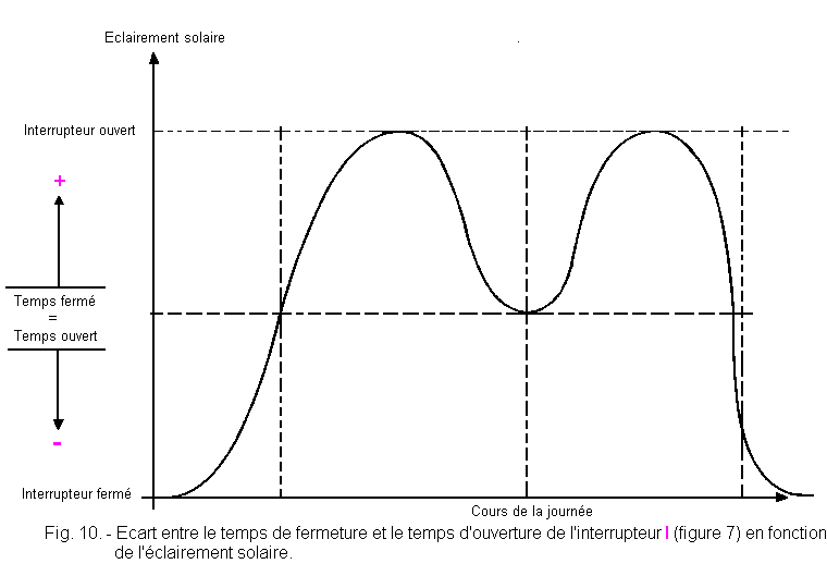
Knowing that the contact (I) opens and closes at the rate given by the vibrator, this number represents the ratio between the closing time and the opening time of the contact I. The opening time corresponds to the extinguished lamp and the closing time with the lamp on.
Consequently, a high number corresponds to a very large closing time with respect to the opening time, which results in a long illumination time of the lamp with respect to the extinction time. Conversely, a small number would correspond to a long extinction time with respect to the illumination time.
When the times are equal (number = 1), the illumination time and the extinction time of the lamp are identical. Figure 10 summarizes this situation.
If the switching frequency at which the switch I vibrates is high, the retinal persistence of the observer will give the observer the illusion that the lamp is on continuously, but with a brightness that will vary according to the ratio, illumination time on extinction time.
According to these data, the digital converter will actuate a relay or vibrator at a specific frequency (in order to avoid the phenomenon of flicker) and according to the external light intensity will act on the duty cycle of this frequency in order to have a report closing time on opening time corresponding to the desired additional illumination.
Finally, we get the curve 2 of Figure 11. It is similar to that obtained with the analog editing. The greater the number of sampled points, the more the curves will be stackable.
In practice, it will suffice to fix the number of points so that the transition from one luminous step to the next is not perceptible. Thus, to the observation of the result it is impossible to discern what is the technique employed.
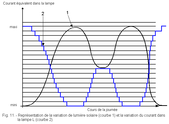
In Figure 11, curve 1 represents the variation of solar light (it is the preceding curve 8) and the points carried on it are the sampling points.
We thus finish this first lesson, in the next, we will study the notions on the sets then on the logical algebra and the functions with N variables and many others ...
 Click here for the next lesson or in the summary provided for this purpose. Click here for the next lesson or in the summary provided for this purpose. |
|
 Previous Page Previous Page |
 Next Page Next Page |
Nombre de pages vues, à partir de cette date : le 27 Décembre 2019
Envoyez un courrier électronique à Administrateur Web Société pour toute question ou remarque concernant ce site Web.
Version du site : 10. 4. 12 - Site optimisation 1280 x 1024 pixels - Faculté de Nanterre - Dernière modification : 02 Septembre 2016.
Ce site Web a été Créé le, 14 Mars 1999 et ayant Rénové, en Septembre 2016.
 Example of Resolved Problem by Analogical Technique then by Digital Technique