 Realization of the Diagram of Inverter Signaling Realization of the Diagram of Inverter Signaling |
 Realization of the Diagram of Signaling by means of electronic symbols Realization of the Diagram of Signaling by means of electronic symbols |
 Footer Footer |
Example of Practical Application of Karnaugh Tables :
4. - EXAMPLE OF PRACTICAL APPLICATION OF KARNAUGH TABLES
4. 1. - Suppose that when the alarm rings in the morning, we want to know how to dress before even opening the shutters.
For this we have a suitable device placed outside and including a thermometer and a barometer and which gives us the following indications : warm weather, mild weather, cold weather, rainy weather.
We decide that in all cases, we will put pants, shoes and a shirt.
It remains now to determine whether it is necessary to put in a jacket, a coat, a raincoat or take an umbrella.
We will call the input variables :
![]() warm weather : c
warm weather : c
![]() nice weather :
d
nice weather :
d
![]() cold weather : f
cold weather : f
![]() rainy weather : p
rainy weather : p
The output variables will be materialized by lamps and will be called :
![]() jacket
: V
jacket
: V
![]() coat : M
coat : M
![]() raincoat : I
raincoat : I
![]() umbrella : P
umbrella : P
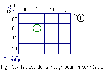
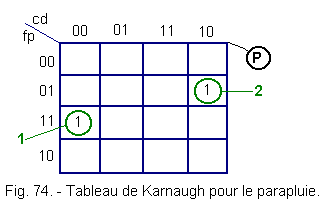
It will be admitted that when it is soft it is a jacket, when it is cold it is put on a jacket and a coat and when it is hot, we put nothing. When it rains, we put a raincoat on the jacket or we take an umbrella when we already have a coat or when it is hot.
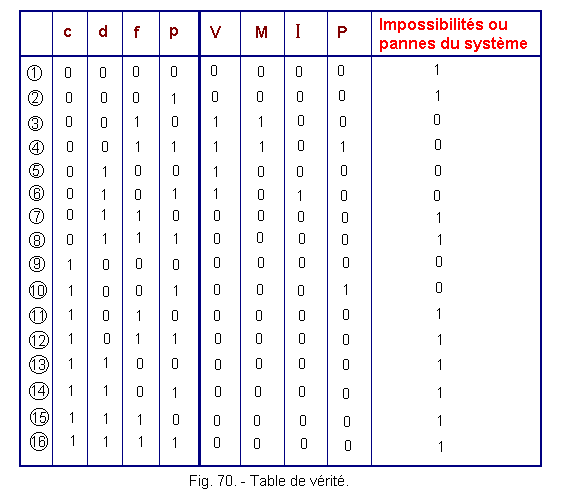
From these postulates, let's establish the truth table of the system (Figure 70).
We have reserved a column that corresponds to the impossibilities. Indeed, it can not be hot and cold for example.
Let's draw Karnaugh's tables from the truth table for each output variable.
4. 2. - KARNAUGH TABLE RELATING TO THE JACKET (Figure 71)
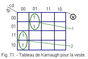
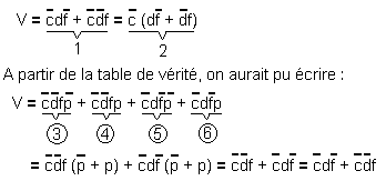
This confirms Karnaugh's picture.
4. 3. - TABLE OF KARNAUGH RELATING TO THE COAT (Figure 72)
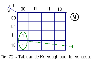
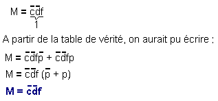
Which confirms Karnaugh's picture.
4. 4. - TABLE OF KARNAUGH RELATING TO THE RAINCOAT (Figure 73)
4. 5. - TABLE OF KARNAUGH RELATING TO UMBRELLA (Figure 74)
![]()
![]() 4. 6. - REALIZATION OF THE INVERTER SIGNALING DIAGRAM
4. 6. - REALIZATION OF THE INVERTER SIGNALING DIAGRAM
Inverter contacts will be used, which will be controlled by the appropriate device mentioned above, as shown in Figure 75.
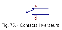
In the example of Figure 75, depending on the position of the switch, we have : d = 1
(high), d = 0 (low) is
![]() ,
in such a way that d = doux and
,
in such a way that d = doux and ![]() = non doux.
= non doux.
![]() a) - Diagram for the jacket (Figure 76)
a) - Diagram for the jacket (Figure 76)
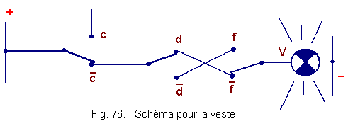
In the diagram of Figure 76, the case is shown ![]() ,
that is to say that the lamp (take your jacket) is lit, since the weather is mild.
,
that is to say that the lamp (take your jacket) is lit, since the weather is mild.
It's easy to understand that the lamp (take your jacket) will also be on for position switches ![]() ,
that is, mild weather.
,
that is, mild weather.
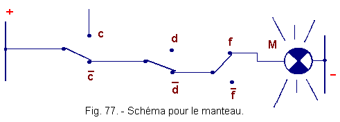
![]() b) - Diagram relating to the mantle (Figure 77)
b) - Diagram relating to the mantle (Figure 77)
Using the same conventions, one can, knowing equality ![]() ,
establish the diagram.
,
establish the diagram.
![]() c) - Diagram relating to the raincoat (Figure 78) :
c) - Diagram relating to the raincoat (Figure 78) :
![]()

![]() d) - Diagram relating to the umbrella (Figure 79)
d) - Diagram relating to the umbrella (Figure 79)
![]()

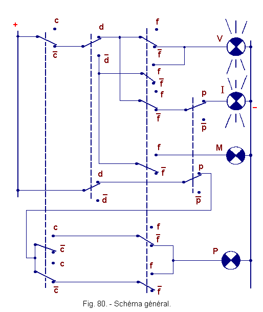
![]() e) - General scheme (Figure 80)
e) - General scheme (Figure 80)
It represents the case where the lamps V and I are lit.
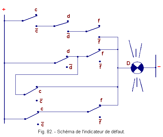
In the truth table (Figure 70), we have provided a column called "impossibilities" or system failures.
There is, indeed, absolute impossibility that the indications hot and cold, soft and cold, warm and soft, etc ... are present simultaneously.
These cases are impossible or the system is down.
From these cases, a lamp can be lit to indicate that the system is not functioning properly.
![]() f) - Karnaugh Detection Default Table (Figure 81)
f) - Karnaugh Detection Default Table (Figure 81)
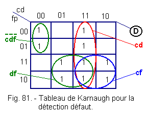
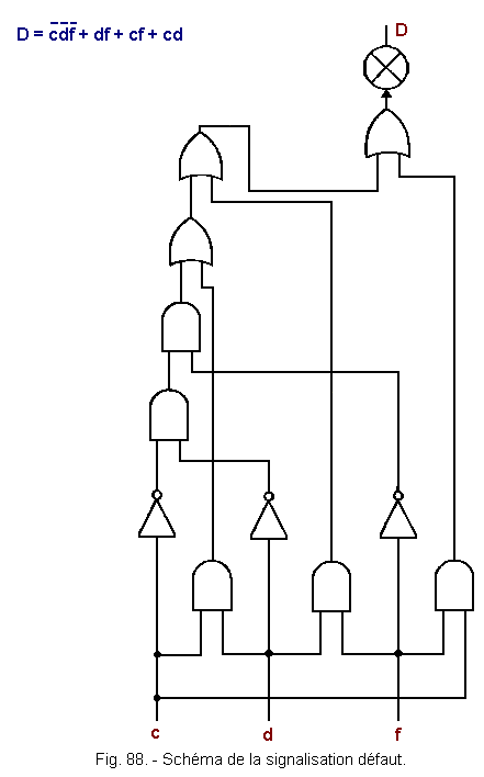
From Karnaugh's table, let's establish the equation of D.

This leads us to the diagram of the fault indicator shown in Figure 82.
![]() 4. 7. - REALIZING THE SIGNALING DIAGRAM USING ELECTRONIC SYMBOLS
4. 7. - REALIZING THE SIGNALING DIAGRAM USING ELECTRONIC SYMBOLS
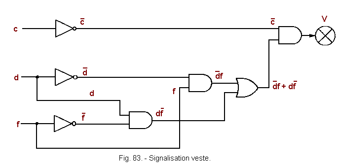
![]() a) - Diagram of the signaling of the jacket (Figure 83)
a) - Diagram of the signaling of the jacket (Figure 83)
![]()
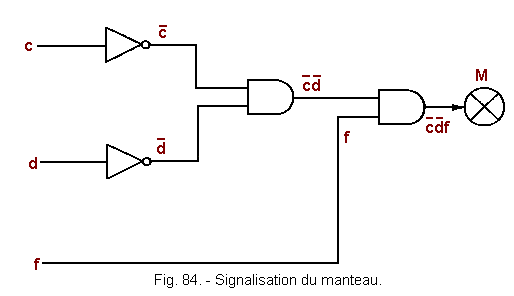
![]() b) - Diagram of mantle signaling (Figure 84)
b) - Diagram of mantle signaling (Figure 84)
![]()
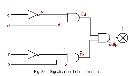
![]() c) - Diagram of the signage of the raincoat (Figure 85)
c) - Diagram of the signage of the raincoat (Figure 85)
![]()
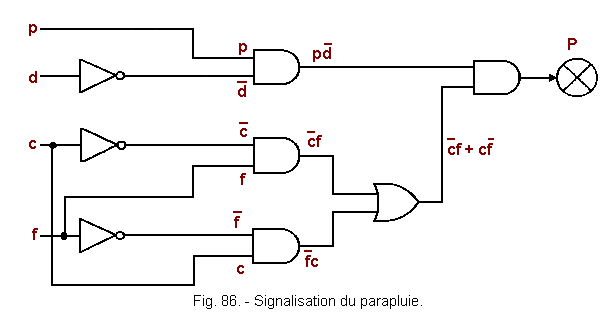
![]() d) - Diagram of the umbrella signaling (Figure 86)
d) - Diagram of the umbrella signaling (Figure 86)
![]()
![]() e) - General scheme (Figure 87)
e) - General scheme (Figure 87)
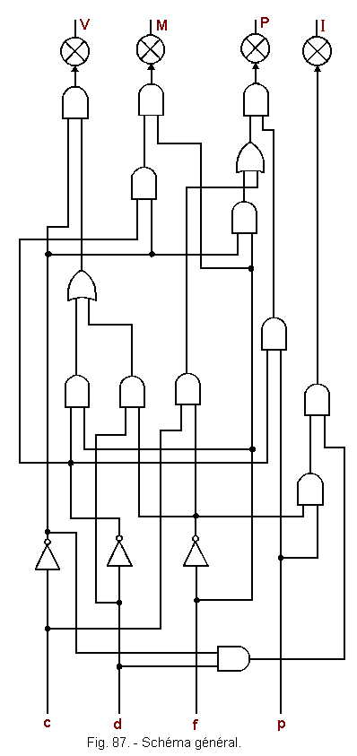
The general scheme will be constituted by the assembly of the other schemes so that the number of logical operators is minimum.
For this purpose, we examine the partial diagrams and knowing for example that ![]() is used in the partial diagrams of V and P can thus use only one inverter to produce the signal
is used in the partial diagrams of V and P can thus use only one inverter to produce the signal ![]() from the variable d. It is thus possible with a little common sense to gather all in a single scheme.
from the variable d. It is thus possible with a little common sense to gather all in a single scheme.
![]() f) - Diagram of the fault signaling (Figure 88)
f) - Diagram of the fault signaling (Figure 88)
In the next theory, we will examine on the one hand new methods for transforming Boolean expressions and on the other logical circuits derived from the three fundamental circuits AND, OR, NO, seen in this theory.
The circuits examined so far are the basis of all so-called "combinatorial" assemblies, that is to say the state (1 or 0) of the outputs depends only on the state of the inputs at the moment we examine mounting.
We finish this second lesson.
 Click here for the next lesson or in the summary provided for this purpose. Click here for the next lesson or in the summary provided for this purpose. |
|
 Previous Page Previous Page |
 Next Page Next Page |
Nombre de pages vues, à partir de cette date : le 27 Décembre 2019
Envoyez un courrier électronique à Administrateur Web Société pour toute question ou remarque concernant ce site Web.
Version du site : 10. 4. 12 - Site optimisation 1280 x 1024 pixels - Faculté de Nanterre - Dernière modification : 02 Septembre 2016.
Ce site Web a été Créé le, 14 Mars 1999 et ayant Rénové, en Septembre 2016.
