FRANCAIS francophone2.gif ANGLAIS


Created the, 12/06/2019

 Updated the, 02/01/2020

Visiteurs N°  


Home
Back to Main Sites New Blog Novelty Search engine Your Shopping Cart For Shopping Your Member Area Bookmarks, Your Favorite Games Static Welcome Page Site in French Web Site in English
Summaries
Basic Electronics Fundamental Technology Test your Knowledge Digital Theoretical Electronics Digital Practical Electronics Digital Electronic Lexicon Data book TTL Data book CMOS TVC Troubleshooting Mathematical
Microcomputers
Theoretical of Microcomputers Test your Knowledge Practical Microcomputers Computer Glossaries
Physical
The light Field of Action Electromagnetic Radiation
Technologies
Classification of Resistances Identification of Resistances Classification of Capacitors Identification of Capacitors
Mathematical Forms
Geometry Physical 1. - Electronic 1. 2. - Electronic 1. 3. - Electrical 1. 4. - Electromagnetism
Access to all our Products
E. T. F. - Volume I - 257 Pages E. T. F. - Volume II - 451 Pages E. T. F. - Volume III - 611 Pages E. T. D. - Volume I - 610 Pages N. B. M. - Volume I - 201 Pages E. T. M. - Volume I - 554 Pages Business at Home Books 34 free pages Our E-books Geometry Software Electronic Components Software
Overview of all our Products
E. T. F. - Volume I - 257 Pages E. T. F. - Volume II - 451 Pages E. T. F. - Volume III - 611 Pages E. T. D. - Volume I - 610 Pages E. T. M. - Volume I - 554 Pages Geometry Software Electronic Components Software
Our Lessons in PDF Formats
Basic Electronics Fundamental Technology Digital Theoretical Electronics Digital Practical Electronics Theoretical of Microcomputers Mathematics
Data Processing
Troubleshooting Win98 and WinXP PC Troubleshooting Glossary HTML and Programs PHP and Programs JavaScript (in progress) Creation of several Sites
Forums
Electronic Forum and Infos Electronic Forum and Poetry
Miscellaneous and others
Form of the personal pages News XML Statistics CountUs JavaScript Editor Our Partners and Useful Links Partnership Manager Our MyCircle Partners Surveys 1st Guestbook 2nd Guestbook Site Directories


Signets :
  Astable Multivibrators based on Transistors         Monostables Multivibrators      Bistables Multivibrators
     Footer  


Multivibrators Based on Transistors :

After having seen the functioning of the astable, monostable and bistable multivibrators with electronic tubes (22nd lesson), we will see the multivibrators based on transistors.

Since the electronic tube assemblies are all studied in the theoretical lessons 21 and 22 (see basic electronic summary)), so grouped in two lessons, it is useless to review them in this theory.

Whether it is a multivibrator with tubes or transistors, there are three types of assembly :

a) The astable multivibrators generating a square wave without any control signal.

b) The monostable multivibrators, delivering a square pulse, after application of a control pulse.

c) Bistable multivibrators providing a sudden change in voltage, whenever an input pulse is applied.

Moreover, the transistors multivibrators have a functioning identical to that of the electronic tube multivibrators.


HAUT DE PAGE 1. - ASTABLES MULTIVIBRATORS

The astable transistor multivibrators work in the same way as the astable electronic tube multivibrators and have the same role.

1. 1. - MULTIVIBRATOR ABRAHAM BLOCH

The reasoning followed for the ABRAHAM BLOCH electronic tube multivibrator can be applied to the assembly of Figure 1.

Multivibrateur_Abraham_BLOCH.GIF

We must remember, however, that for a PNP transistor to drive, its base must be at a negative potential with respect to the transmitter.

This arrangement has a serious disadvantage at low frequencies.

Indeed, to obtain these frequencies, we must increase the value of the elements constituting the RC link circuits.

Now, we are limited by the value of the basic resistors of the transistors ; these must have a rather low value, so that the base current is important and allows the saturation of the transistor.

We must then use capacitors of high capacity, which are almost obligatorily of the electrochemical or electrolytic type, therefore with high temperature coefficients, large leaks and fairly large dispersions.

To avoid this disadvantage, we can use pairs of transistors mounted in DARLINGTON.

The amplification coefficient β of this arrangement is very much greater than the β of a single transistor (several tens of times) and we will be able to use much higher basic resistances and consequently reduce the value of the capacitors.

The circuit shown in Figure 2 allows for extremely asymmetrical multivibrators, making the capacitors C1 and C2 very unequal, which is very disadvantageous in the case of the assembly of Figure 1 (recovery of the collector potential not completed at the time of switching).

Multivibrateur_astable_monte_en_Darlington.GIF

1. 2. - MULTIVIBRATOR WITH TRANSMITTER COUPLING

This circuit is represented in figure 3 and we immediately see the analogy with the cathode-coupled tube multivibrator, (see 22nd lesson).

Multivibrateur_astable_a_couplage_emetteur.GIF

The assembly comprises a single time constant link, R1C1, the other being replaced by the coupling due to the resistor RE common to the two transmitters.

The highly conductive transistor, creates across the RE a voltage drop sufficient to block the other transistor.

But the load of C1 flows through R1, and after a time function of the time constant R1C1, the mounting switches. The blocked transistor becomes conductive and the driver blocking.

1. 3. - MULTIFIBRATOR WITH UNIJUNCTION TRANSISTOR :

By using a unijunction transistor (UJT), we can realize an astable multivibrator according to the diagram of figure 4.

Multivibrateur_astable_Unijonction_UJT.GIF


The waveforms noted at points A, B and C of this arrangement are indicated by the three curves of Figure 5.

Formes_d_ondes_du_multi_astable_UJT.GIF

At time t0, the unijunction transistor has no emitter current. Diode D is conductive and the potential of point A is slightly greater than zero.

That of point B (transmitter of U.J.T.) rises, since a current, passing through R2, charges capacitor C.

This charging current passing through C goes, by the diode D, to ground, superimposed on it with the current flowing through the resistor R1.

At time t1, the point B reaches a potential equal to the peak voltage of the UJT. It starts, and the current between its base B1 and its base B2 increases, causing an increased voltage drop in the resistor R3.

The potential of the point C goes from the value + E to the value + e.

The current flowing through resistor R2 goes to the transmitter of the UJT and the capacitor can no longer charge.

The lowering of the potential of this emitter, transmitted by the capacitor C to the point A, makes this point negative : the diode D is blocked.

The current flowing through R1 increases by the fact that the point A is now at a negative potential, no longer crosses the diode, but discharges the capacitor C.

The discharge current is superimposed on the emitter current and maintains the emitter potential at a substantially constant value.

As capacitor C discharges, the voltage of point A rises to 0.

At time t2, it reaches and even slightly exceeds this value. The diode D then becomes conductive and the current flowing in R1 no longer goes to the transmitter of the UJT by discharging C, but flows to ground through the diode D.

Under these conditions, the current flowing in the resistor R2 can recharge the capacitor C. The emitter current of the UJT decreases and it decays.

The voltage at point C rises from the value + e to the value + E.

The voltage at point B goes back exponentially towards the value of the peak voltage of the UJT, that it will reach at time t3. At this moment, the transistor starts and everything takes place according to a periodic law.

Before switching to MONOSTABLES multivibrators, note that all ASTABLES multivibrators are characterized by the absence of steady state and a relatively precise operating frequency.

But this defect can become a quality, because one can easily impose the multivibrator a frequency, with the help of pulses causing a premature switch : it is the synchronization.

Let's give an example of synchronization, in an application known to everyone : Television.

In this technique, it is indeed necessary to ensure the coincidence of the scans of the receiver and the camera of shooting.

For this purpose, pulses are transmitted by the transmitter Television and applied to the scanning stages, so as to enslave them in frequency.

This subject that comes out of the basic course is obviously treated in detail in the TV Specialization lessons. It is cited here only as an example of application of astable multivibrators.

HAUT DE PAGE 2. - MONOSTABLE MULTIVIBRATORS

As their name implies, monostable multivibrators have a stable state of operation and an unstable state. More precisely, after application of a control signal, they pass from the stable state to the unstable state but automatically return to the original state : the STABLE position.

They remain in this state until a new control pulse comes back to the unstable state and so on.

2. 1. - MONOSTABLE MULTIVIBRATOR FUNDAMENTAL

As indicated above, the monostable multivibrator of Figure 6 has a stable state and an unstable or quasi-stable state.

Multivibrateur_monostable_transistors.GIF

A trip pulse switches the mount to the unstable state. Then, the assembly returns of itself to the stable state.

The circuit of Figure 6 is derived from the astable multivibrator ABRAHAM BLOCH. One of the capacitive crossover couplings was simply replaced by a resistive coupling. In fact, there is, in parallel on the coupling resistor, a capacitor which will be ignored for the moment.

In the stable state, T2 leads to saturation and T1 is blocked.

The blocking of T1 is obtained, thanks to the current flowing in the bridge of the resistances formed by Rc2, R1 and R2.

This voltage (Vb1) follows the voltage variations of the T2 collector. When Vc2 = - E (T2 blocked), Vb1 is slightly negative ; when Vc2 = 0 (T2 at saturation), Vb1 is positive (T1 blocked).

The transistor T2 is biased by the resistor Rb2, calculated so as to drive the transistor T2 to saturation.

The negative trigger pulse unlocks transistor T1. The variation of the collector potential of T1 is retransmitted at the base of T2 and it is blocked.

The capacitor C1 can then be discharged through T1, the source - E and the resistor Rb2.

The discharge current maintains a positive polarity voltage on the basis of T2 which does not conduct.

When the discharge of C1 is complete, the basic potential T2 becomes negative and T2 leads to saturation.

As the collector voltage of T2 decreases, this variation is transmitted by R1 and R2 on the basis of the transistor T1 which is blocked again.

The phenomenon is not completely finished, it is indeed that the capacitor C1 is recharging. It does this through the resistor Rc1 and the base-emitter junction of the transistor T2.

After a time equal to three times this time constant, the capacitor is charged to 95% of its limit value ; it is considered at this time that the assembly can work, if it then applies a new trigger pulse, in circumstances very similar to those of the previous operation.

The time taken by the capacitor to recharge is called RECOVERY TIME.

Figure 7 shows the different voltage curves that we can see on this assembly.

Differentes_courbes_du_monostable.GIF

The input capacitance of transistor T1 reduces the gain at high frequencies, which increases the switching time.

In practice, the attenuation due to the input capacitance is compensated by the paralleling of C2 (in dotted lines in Figure 6) on R1.

This capacitor, although not essential to the operation of the univibrator, accelerates the tilting of the latter and make it easier, by transmitting better to the base of T1 the steep face of the square voltage appearing on the T2 collector.

The fundamental monostable multivibrator is obviously very stable in frequency, since it is controlled by triggering pulses.

The time during which the assembly remains in the unstable state (T2 blocked, T1 leading) is determined by the time constant of the discharge circuit of the capacitor C1 (it is considered that the resistances of the base-emitter junction of T2 and the source - E are negligible).

The duration of the unstable state is given approximately by the formula : t = 0.7 x (C1 x Rb2).

2. 2. - COUPLING UNIVERATOR BY TRANSMITTERS

This assembly, represented in Figure 8, is identical to the electronic tube circuit that we studied in the theoretical lesson 22.
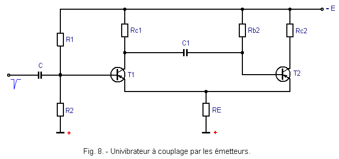
Multivibrateur_monostable_a_couplage_emetteur.GIF

The transistor T2 is biased by the resistor Rb2, so as to be highly conductive. The transistor T1 is substantially blocked.

The voltage drop in RE reinforces this state of affairs and in the absence of the external signal, there is no reason for this situation to change. The assembly remains stable.

If we apply a negative pulse on the basis of T1, it becomes momentarily conductive and transmits, through C1, a blocking pulse to transistor T2.

The assembly switches and the capacitor C1 discharges through T1, RE, the source - E and the resistor Rb2.

The discharge current maintains a base voltage Vb2 positive relative to that of the T2 emitter which remains blocked.

At the end of a certain time, determined by the time constant Rb2 and C1, the charge of C1 passed through Rb2.

T2 becomes conductive again and re-blocks T1 by the current in RE. The assembly has returned itself to a stable state.

A new control pulse will trigger the switchover and return to the idle state.

The circuit of Figure 9 is also a transmitter-coupled univibrator, but the operation has been improved by the addition of a diode D and two resistors R3 and R4.
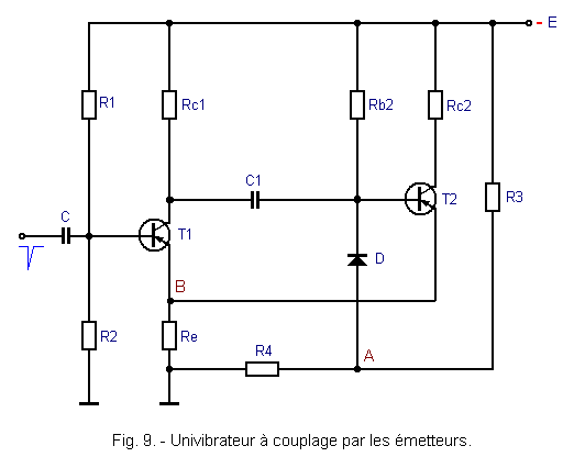
Univibrateur_a_couplage_emetteurs.GIF

It is preferable, for the stability of the assembly, to ensure that the transistor T2 is not at saturation in its conduction state.

Diode D limits the basic negative potential to the value set at point A by the resistor bridge R3 and R4. For the diode to act, the potential of point A must be more negative than that of point B.

Indeed, if the base voltage is not negative compared to that of the transmitter, the transistor T2 never leads.

Depending on the value of the constant potential of the base T1 (potential fixed by the voltage divider bridge formed by R1 and R2), it is possible to vary the conduction of T1 and consequently modify the duty cycle of the output signal.

If this potential is too low, the monostable does not work : when T2 tends to be blocked, the current passing in T1 is low (internal resistance of the high transistor). The discharge current of C1 then produces in Rb2 a voltage drop that is too low to keep T2 locked.

If, on the other hand, the basic potential of T2 is too high, the whole enters permanent oscillations and becomes a multivibrator with coupling by the emitters.

The basic potential of T1 must therefore be between these two critical values.

Unlike the case of electronic tubes, the transmitter-coupled univibrator, if it has the advantage of not requiring a positive voltage source, seems to be discouraged.

The fundamental monostable multivibrator is preferable from the point of view of operational safety, because of the large margins of blocking of transistors T1 and T2.

Monostable multivibrators provide an output pulse for each input pulse.

They mainly serve :

1°) to shape pulses to make them become rectangular signals of amplitude and duration invariable.

2°) delaying the trigger pulse applied to the input ; the triggering of the subsequent stages is then produced by the trailing edge of the output pulse.

Now let's look at the third category of multivibrators : BISTABLES multivibrators, which as their name suggests have two stable states.

HAUT DE PAGE 3. - BISTABLE MULTIVIBRATORS

Bistable multivibrators have two stable states. This means that initially, one transistor is blocked and the other driver.

After applying a control pulse, the blocked transistor becomes conductive and the conductive transistor is blocked. A second control pulse brings the fixture back to its original state and so on.

3. 1. - BISTABLE MULTIVIBRATOR OF THE TYPE "ECCLES JORDAN"

The diagram of a bistable transistor type "Eccles Jordan", is shown in Figure 10. Each transistor controls from its collector, the base of the other, by a continuous link, made of a bridge of two resistors R1 - Rb2 and R2 - Rb1.
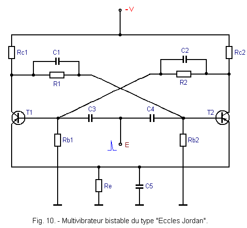
Multivibrateur_bistable_du_type_Eccles_Jordan.GIF

The values of the resistors and the supply and bias voltages are chosen so that, when one transistor is blocked, it causes the other to lead (in general to saturation) ; when one transistor is charging, it causes the other to block.

The assembly is carried out as symmetrically as possible, the two transistors have the same characteristics, the collector resistances are equal and the resistor bridges are made with paired elements.

As soon as the power is turned on, both transistors tend to drive. Although the mounting is symmetrical, the two collector currents are not exactly equal. The base voltages resulting from the currents flowing in the resistor bridges R1 - Rb2 and R2 - Rb1 are unbalanced.

Very quickly and thanks to the cumulative effect, the assembly is in a stable state (for example T1 driver and T2 blocked). It is this state that we will call "state of rest".

Let's send through C3 and C4, a positive trigger pulse.

The transistor T1 sees its base becoming positive with respect to its transmitter and it locks. The transistor T2 already blocked does not undergo any change in operation during the duration of the pulse.

From the beginning of the blocking of T1, the collector potential Vc1 begins to rise. This rise towards the negative value - V is transmitted to the base of T2, partly by the bridge R1 - Rb2, and totally by the capacitor C1.

The base of T2 becomes negative with respect to the transmitter and the transistor T2 begins to drive.

The collector potential of T2, initially at the value - V, changes to a less negative value (- V - Ic2 x Rc2).

The positive variation transmitted to the T1 base by the R2 - Rb1 bridge and C2 blocks T1.

T2 collector voltage remains low (conductive T2), the voltage brought by the bridge R2 - Rb1 on its base T1, is not sufficient to unlock T1.

We thus obtain a new stable state which is : T1 blocked, T2 conductive.

A new positive impulse will block T2. Raising the collector voltage Vc2, transmitted by the link circuit to the T1 base, unlock the latter. The assembly returned to the state of rest.

The bistable multivibrator can be controlled indifferently by positive or negative pulses applied to the bases of the transistors.

Another solution is to send the control pulses on the collectors of the transistors through two diodes.

The scheme of Figure 11, shows a bistable Eccles Jordan, controlled in this way.
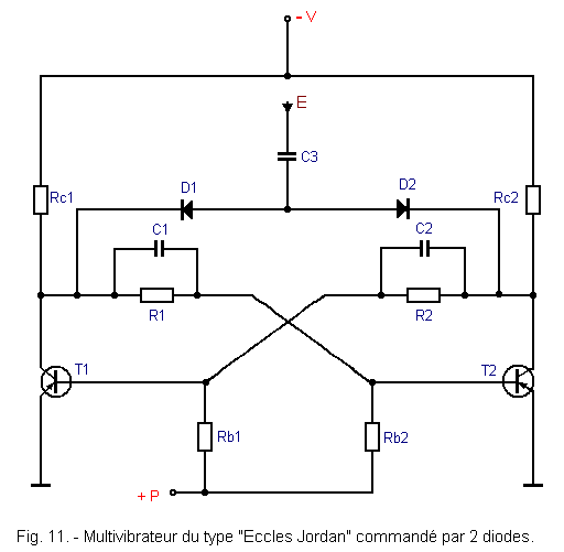
Multivibrateur_bistable_du_type_Eccles_Jordan_1.GIF

In this arrangement, the transmitters are connected directly to the ground. The polarization of the transistors is obtained thanks to a positive voltage + P applied to the bases of the transistors, through Rb1 and Rb2.

The diodes D1 and D2 make it possible to "direct" the control pulses on the collector of the transistor which is blocked.

Suppose T1 is conductive and T2 blocked. Apply by the capacitor C3, a positive pulse on the anodes of the two trigger diodes.

Diode D2 has its cathode connected to the T2 collector. The latter being blocked, the collector voltage is close to the negative potential - V.

The diode D2 is therefore highly conductive and it transmits without attenuation the control pulse.

On the other hand, the diode D1 has its cathode brought to a very little negative potential (the transistor T1 leads to saturation and the collector voltage is low).

When the positive pulse arrives, the diode D1 is still conductive, but less than D2. The pulse that appears on the T1 collector is attenuated by the resistance presented by the diode D1.

The positive pulse through D2 will be transmitted by R2, Rg1 and C2, the base of the transistor T1, which will lock. The assembly switches at this moment into the other stable state, that is to say : T1 blocked and T2 conductive.

We end our explanations on the astable, monostable and bistable multivibrators based on transistors and we will take between some special circuits, negative clippers, positive clippers and mixed clippers.


Nombre de pages vues, à partir de cette date : le 27 Décembre 2019

compteur visite blog gratuit

Mon audience Xiti


Send an email to Corporate Webmaster for any questions or comments about this Web Site.

Web Site Version : 11. 5. 12 - Web Site optimization 1280 x 1024 pixels - Faculty of Nanterre - Last modification : JANUARY 02, 2020.

This Web Site was Created on, 12 JUNE 2019 and has Remodeled, in JANUARY 2020.