FRANCAIS francophone2.gif ANGLAIS


Created the, 12/06/2019

 Updated the, 02/01/2020

Visiteurs N°  


Home
Back to Main Sites New Blog Novelty Search engine Your Shopping Cart For Shopping Your Member Area Bookmarks, Your Favorite Games Static Welcome Page Site in French Web Site in English
Summaries
Basic Electronics Fundamental Technology Test your Knowledge Digital Theoretical Electronics Digital Practical Electronics Digital Electronic Lexicon Data book TTL Data book CMOS TVC Troubleshooting Mathematical
Microcomputers
Theoretical of Microcomputers Test your Knowledge Practical Microcomputers Computer Glossaries
Physical
The light Field of Action Electromagnetic Radiation
Technologies
Classification of Resistances Identification of Resistances Classification of Capacitors Identification of Capacitors
Mathematical Forms
Geometry Physical 1. - Electronic 1. 2. - Electronic 1. 3. - Electrical 1. 4. - Electromagnetism
Access to all our Products
E. T. F. - Volume I - 257 Pages E. T. F. - Volume II - 451 Pages E. T. F. - Volume III - 611 Pages E. T. D. - Volume I - 610 Pages N. B. M. - Volume I - 201 Pages E. T. M. - Volume I - 554 Pages Business at Home Books 34 free pages Our E-books Geometry Software Electronic Components Software
Overview of all our Products
E. T. F. - Volume I - 257 Pages E. T. F. - Volume II - 451 Pages E. T. F. - Volume III - 611 Pages E. T. D. - Volume I - 610 Pages E. T. M. - Volume I - 554 Pages Geometry Software Electronic Components Software
Our Lessons in PDF Formats
Basic Electronics Fundamental Technology Digital Theoretical Electronics Digital Practical Electronics Theoretical of Microcomputers Mathematics
Data Processing
Troubleshooting Win98 and WinXP PC Troubleshooting Glossary HTML and Programs PHP and Programs JavaScript (in progress) Creation of several Sites
Forums
Electronic Forum and Infos Electronic Forum and Poetry
Miscellaneous and others
Form of the personal pages News XML Statistics CountUs JavaScript Editor Our Partners and Useful Links Partnership Manager Our MyCircle Partners Surveys 1st Guestbook 2nd Guestbook Site Directories


Signet :
     Footer  


Alternate Current Electric Power :

2.- ELECTRICAL POWER IN ALTERNATING CURRENT CIRCUITS :


In a circuit traversed by a direct current, the power P that it dissipates is expressed by the relation : P = V x I.

In a circuit traversed by an alternating current, the voltage and the intensity vary at every moment, and the instantaneous power is expressed by the relation p = v x i ("v" is the instantaneous tension and "i" the instantaneous intensity).

To determine the power in a circuit, three cases must be considered.

2. 1. - FIRST CASE : VOLTAGE AND CURRENT ARE IN PHASE

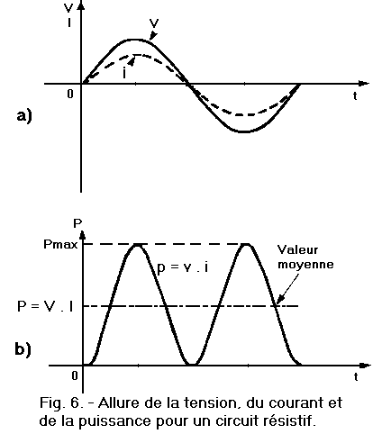
This is the case of a purely resistive circuit. The voltage and current have the appearance shown in Figure 6-a.

 Allure_Tension_Courant_Resistif

To obtain the curve representative of the power (Figure 6-b), it suffices to multiply point by point the value of the voltage (v) by that of the intensity i.

This curve is a sinusoid located entirely above the abscissa axis since the product (vi) is always positive. On the other hand, the frequency of this sinusoid is twice that of (v) or of i.

The power (p) is equal to 0 when v = i = 0. It is maximum when (v) and (i) are maximum.

Pmax = Vmax x Imax

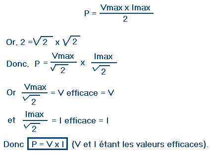
The average value (P) of the power considered corresponds to half of Pmax, namely :

Puissance_active

This relation is identical to that obtained in the case of a direct current.

Since the power involved in the resistive circuit can be used to produce a job, it is called active power. It is measured in watts and is indicated by the symbol P.

2. 2. - SECOND CASE : TENSION AND CURRENT ARE DEPHASES OF 90°

Consider the case of pure inductance.

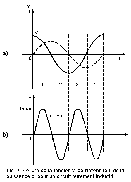
The voltage (v) is in advance of 90° with respect to the intensity (i) as represented in Figure 7-a.

As in the previous case, it is sufficient to multiply at each instant the voltage (v) by the intensity (i) to obtain the curve representative of the power P (Figure 7-b).

Tension_Intensite_Puissance_Circuit_inductif

We note that the resulting sinusoid is the same as that of Figure 6-b, but this time it is centered on the x-axis. Indeed, in the first quarter of period, the tension as the intensity are positive ; the power is so too. In the second quarter of the period, the intensity remains positive, but the voltage becomes negative, the power is therefore negative. A similar analysis can be done for the third and fourth quarters of the period.

The average value of the power is zero. If we want to calculate the energy expended in the pure inductance, we find that it is zero since the power is zero.

This seems contradictory to the principle that a generator supplies energy to the receiver circuit connected to it.

We know that for a resistive circuit, the energy consumed is transformed and dissipated in the form of heat.

In the case of a purely inductive circuit, the energy supplied by the generator is stored in the magnetic field created by the inductor when the current increases.

This magnetic field dissipates when the current decreases and the previously supplied energy is returned to the generator.

The power involved in a purely inductive circuit being zero, it produces no work. It's called reactive power. It is denoted by the symbol Q (Pr is also found) and is measured in reactive amperes (VAR).

2. 3. - THIRD CASE : VOLTAGE AND CURRENT ARE PUNCHED FROM AN ANGLE PHI INCLUDED BETWEEN 0° AND 90°

This is the most general case.

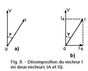
The current and the voltage are then represented by two vectors V and I phase-shifted together at a certain angle PHI, as shown in Figure 8-a.

To find the active power P absorbed by the circuit, let's decompose the vector I into two vectors : the first IA in phase with the voltage V and the second IQ phase-shifted by 90° as shown in Figure 8-b.

One can imagine that the circuit is traversed by two distinct currents (IA and IQ) out of phase with each other by 90°.

Decomposition_du_vecteur_I_IA_IQ 

The current IQ is 90° out of phase with the voltage V. This current IQ does not perform any useful work. It only determines an alternating exchange of energy between the generator and the circuit.

It is only the current IA in phase with the voltage V which produces a useful work.

The product of the voltage V by the current I therefore represents an apparent power absorbed by the inductive and resistive circuit. Only part of this apparent power, denoted S, is used by the circuit in providing useful work.

This apparent power (S) is expressed in volts amperes (VA).

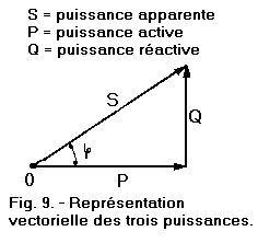
The three powers (active, reactive and apparent) are linked by a relation that can be deduced from Figure 9.

These three vectors representing the three powers form a right triangle. The hypotenuse represents the apparent power S and both sides represent the active power P and the reactive power Q.

 Vectorielle_des_3_puissances

Using trigonometric relations, we deduce :

Calcul_Puissance_Apparente

The cos factor PHI represents the fraction (less than 1) of the apparent power (S) actually used by the circuit.

This cos factor PHI is called circuit power factor and is expressed by the relation :

cos PHI = P / S

We can also express these powers in another form. We have seen that the apparent power is the product of the voltage V by the current I. We can therefore write :

 Puissance_apparente

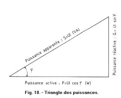
We can then enter this value in the power triangle (Figure 10).

We have just seen that the active power P is given by the relation :

P = S cos PHI

By replacing S with its value VI, we obtain

Puissance_active2

 Triangle_des_puissances

On the other hand, the reactive power Q is given to us by the relation :

Q = S sin PHI

Who becomes :

Reactive power : Q = VI sin PHI (VAR)

And finally :

Cos PHI = Active power / Apparent power


Nombre de pages vues, à partir de cette date : le 27 Décembre 2019
compteur visite blog gratuit


Mon audience Xiti


Send an email to Corporate Webmaster for any questions or comments about this Web Site.

Web Site Version : 11. 5. 12 - Web Site optimization 1280 x 1024 pixels - Faculty of Nanterre - Last modification : JANUARY 02, 2020.

This Web Site was Created on, 12 JUNE 2019 and has Remodeled, in JANUARY 2020.