By replacing L = 4 H with a resistance of 1256 Ω, one could expect to obtain the same result from the point of view of attenuation of the AC component.
In practice, the result is less good because the coil has the property of opposing current variations, which is not the case of a resistor. However, RC cells are sufficiently effective in practice.
Using the same example, we see that in the double-wave array, where the AC component has a frequency of 100 Hz, the result is considerably improved.

Of course, the capacitor C2 has the same effect, with respect to the load of the power supply, as the capacitor C1 with respect to L or R.
For the calculation of the attenuation of the AC component (the latter causing humming in an amplifier BF, also called snoring voltage), the value of the DC output voltage US and also of the current delivered must be taken into account. by the power supply and absorbed by the load.
It is obvious, indeed, that the AC component depends on the DC output voltage, because the higher it is, the higher the AC voltage required, is of significant amplitude.
As for the current delivered by the power supply, it is equally easy to understand that the smaller the power, the more capacitor (when discharged) is able to maintain a constant flow rate.
The theoretical calculation of the attenuation, which is very complex, must take into account the charging and discharging times of the capacitor, as a function of the voltage and current parameters.
We will not discuss the details of these calculations outside the scope of this lesson, especially since the results obtained are often incorrect in practice, depending on the nature of the load that can be partially resistive, inductive and capacitive.
However, to have a rough idea, perfectly valid in practice, one can simply calculate the snoring voltage using the formulas below.
a) - Single alternating circuit, with filter having only one capacitor :
Vr = (4 x I / C1) x  2
with :
Example : A power supply with a current of 60 mA. The filter capacitor has a value of 50 µF.
Vr = (4 x I / C1) x  2
= (4 x 60 / 50) x 1,41 = 6,7 Volts.
b) - Full-wave circuit, with filter having only one capacitor :
Vr = (4 x I / C1)
Example : Same data as in the previous example.
Vr = (4 x I / C1) = 4 x 60 / 50 = 4,8 Volts
c) - Single
alternating
circuit, with filter comprising two capacitors and a coil (see Figure 19).
Vr = (4 x I / C1 x C2 x L) x  2
with :
-
I en mA
-
C en µF
-
L en H
(henry).
Example : Same data as in the previous example, plus C2 = 50 µF et L = 2 H.
Vr = (4 x I / C1 x C2 x L) x  2
= (4 x 60 / 50 x 50 x 2) x 1,41 = 67 mV
d - Full-wave circuit, with filter comprising two capacitors and a coil (see Figure 19) :
Vr = 4 x I / C1 x C2 x L
Example : Same data as in the previous example :
Vr = 4 x I / C1 x C2 x L = 4 x 60 / 50 x 50 x 2 = 48 mV
In the last two formulas, replace L (value in Henry of the coil) by R (value of the resistance in place of the coil).
In this case, we then express :
Example : Same example as above, but with R = 1,200 Ω instead of L = 2 H.
Vr = 4 x I / C1 x C2 x R = 4 x 60 / 50 x 50 x 1,2 = 80 mV
This value of 80 mV, representing the AC voltage, superimposed on the DC output voltage is perfectly acceptable in the vast majority of cases.
Also, the fact of using a coil rather than a resistance depends mainly on the permissible voltage drop, caused by the filter cell.
Looking at Figure 19, it can be seen that the entire current absorbed by the load (which will be connected to the output terminals US) passes through the coil L or the resistor R.
This obviously results in a voltage drop (U = R x I) and therefore the DC voltage US available, is less important.
Let's take an example with common values.
A filter coil of 4 Henrys for example, of excellent quality, has an ohmic resistance (due to the winding constituting the winding) of the order of 40 Ω.
Instead of this coil, it can take a resistance of about 1500 Ω.
If the current output is 60 mA for example, in the first case, the voltage drop will be :
U = R x I = 40 x 0,06 = 2,4 V
Thus, with a DC output voltage of 250 Volts, the load voltage US will be :
250 - 2,4 = 247,60 Volts about
With the resistance of 1500 Ω, and under the same conditions, the voltage drop will be :
U = R x I = 1500 x 0,06 = 90 Volts
The US voltage under charge will then have value :
250 - 90 = 160 Volts
If the current required was even more important (for example 100 mA instead of 60 mA), the voltage drop would be prohibitive (1500 x 0.1 = 150 Volts).
In conclusion, a filtering resistor (inexpensive and space-saving element) is used when the current that the supply must supply is relatively small.
In the opposite case, a filtering coil is adopted.
In practice, there are power supplies with CRC cells, for maximum currents of the order of 60 to 80 mA.
Beyond these values, there are CLC cells.
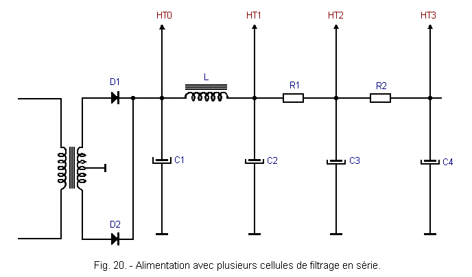
In both cases, when the power supply must supply current to several loads, several filter cells in series can be encountered.
This avoids the influence of one load on the other (this is called decoupling circuits).
The assembly is as shown in Figure 20.

In this example, if :
and if the currents requested are :
-
HT1 = 100 mA
-
HT2 = 50 mA
-
HT3 = 20 mA
We will have, in the case of a DC output voltage of 250 volts :
-
HT1 = 250 - (40 x 0,1) = 246 Volts
-
HT2 = 246 - (1000 x 0,05) = 196 Volts
-
HT3 = 196 - (500 x 0,02) = 186 Volts
Of course, each cell improves filtering and adding effects ; the snoring voltage on HT3 will be lower than on HT2, itself lower than on HT1.
Finally, since there are circuits that can be powered with a poorly filtered voltage, it can be taken directly on the cathodes, across C1 (HT0).
By neglecting the internal resistance of the rectifiers, the voltage drop will be zero, therefore : HT0 = 250 Volts.
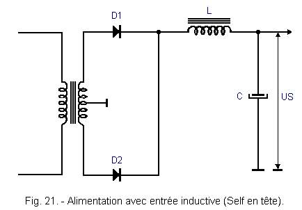
 4. - FILTER CELL WITH INPUT SELF
In the cells we examined, the first element was always capacitor C1.
For this reason, these cells are called capacitive input cells.
In the vast majority of cases, these are the ones found on power supplies.
However, on some montages, SELF is placed as an input element.
The diagram of this kind of circuit is represented in Figure 21.

This type of cell is adopted for gas and mercury vapor tubes (Industrial Electronics).
With these, low internal resistance, the adoption of a capacitor of high capacity, would give rise when it is discharged at an excessive charge current, which can destroy these tubes.
The SELF filter in the HEAD, decreases the AVAL ripple rate (after the coil) but increases the ripple rate AMONT.
The residual hum at the filter outlet, is calculated as above, using the formula :
Vr = 4 x I / L x C
To have a constant DC output voltage, with a low load, the input choke must have a minimum value in henries, much larger than that required for a normal load.
However, a high value of L means that the magnetic circuit is bulky (a lot of iron), and that the winding (a lot of copper) has a significant ohmic resistance.
Since it is necessary to reduce this resistance to avoid unnecessary voltage drop and power dissipation, a slip self is usually used, that is, a coil with a reduced, or even zero, gap.
Such a self has the required value when the flow is low, but falls to about one-third or more, when the flow is normal.
This phenomenon is due to the partial saturation of the iron, in which the magnetic flux remaining almost constant can not induce a counter-electromotive force in the coil, which thus loses its power to oppose the variations of current, that is to say to say, loses its inductive value.
It should be noted that in both types of cells (capacity or self at the top), the coil must be provided for the maximum current required.
Otherwise, there will be a heating (or even destruction) of the winding.
In the filter cells with capacity at the head, when L is replaced by a resistor, it must be able to dissipate heat, the power resulting from the resistance value of R and the current (P = R x I²).
Thus, in the case of a power supply 80 mA, it will be necessary to choose a filter choke capable of supporting this intensity.
If the choke is replaced by a resistance of 1500 Ω for example, it must be able to dissipate a power of :
P = R x I² = 1500 x 0,08² = 9,6 Watts see 10 Watts in practice.
We will now see other power circuits, commonly used in different applications of electronics.


 Filtering cell with input self
 Click here for the next lesson or in the summary provided for this purpose.
 Next Page