Assembly of the Power Supply and wiring of the Printed Circuit :
3. - ASSEMBLY OF THE POWER SUPPLY
As a first step, you will mount some power components on the PCB and attach it to the digilab. In a second step, you will proceed to a control off the circuit. Finally, you will carry out the transformer assembly and the live test of the power supply.
Perform the various operations with great care and attention and follow the instructions below.
3. 1. - WIRING THE PRINTED CIRCUIT
Referring to Figure 3, do the following :
a) Insert the 4700 µF - 25 V electrolytic capacitor C1 at the intended location on the circuit board. Observe the polarity of this capacitor. Then solder the two terminals of it to the copper pellets and cut the excess part.
b) Respecting the polarity of the 4.7 µF - 10 V C3 tantalum electrolytic capacitor, solder it to the printed circuit board.
c) Solder the ceramic capacitor C2 of 100 nF (or 0.1 µF) on the printed circuit.
d) Solder on the printed circuit the resistance R1 of 220 Ω - 1 / 4 W tolerance 5% (red - red - brown - gold).
The bridge rectifier has four terminals, as shown in Figure 4.
Two are marked by the usual symbol ~
and constitute the input on which is applied the AC voltage taken from the secondary of the transformer.
The other two terminals labeled (+)
and (-) are the outputs connected to the terminals of the filter capacitor C1. Sometimes the rectifier bridge has a landmark that indicates the respective position of the (+) and (-) terminals.
e) Solder the rectifier bridge DR1 type B 40C 3700 / 2200 on the PCB respecting the polarity of its two output terminals (+) and (-).
Now you will wire the LM 340T5 regulator. It is provided with three electrodes. Figure 5 shows the regulator seen from the front and side.
Pin 1 on the left is the input to which the unregulated voltage is applied. Central pin 2 is connected to ground.
Pin 3 is the output that provides the regulated voltage. The metal plate connected to the pin 2 is pierced with a hole for fixing on a radiator. The latter allows the heat dissipation generated by the integrated circuit.
In this assembly, the radiator will be constituted by the metal front of the digilab.
For now, perform a temporary mechanical assembly of the regulator by following the following instructions :
f) Prepare the integrated circuit as shown in Figure 6-a. Use the flat pliers to bend the three electrodes 90° to the side of the front face. The fold line is located approximately 3 mm from the regulator housing.
g) Turn the circuit board over and insert the pins of the integrated circuit on the copper tracks side into the holes provided. The regulator mounting hole must match the hole on the PCB as shown in Figure 7-a. Do not perform any welding at this time.
h) Secure the regulator to the printed circuit board with a Ø 3 x 9 mm threaded hex spacer and two Ø 3 x 4 mm screws, as shown in figure 7-b.
Tighten both screws securely ; thus, the metal plate of the integrated circuit will be correctly positioned relative to the printed circuit.
i) Weld the three pins of the regulator onto the copper pads and cut off the excess portion that pops out on the un-coppered side of the circuit board.
To complete the assembly on the printed circuit, you still have to solder a connector and some connection wires that will be used to connect to the other components of the power supply.
j) Position the 3 pins male connector as shown in Figure 8 and solder the 3 pins to the circuit board.
k) Cut two pieces of red flexible wire of 0.5 mm2 section and about 30 cm long. Strip the ends 3 to 4 mm, then twist the two wires together. Then insert the wires from one end of the twist into the holes next to the rectifier bridge (Figure 8) and solder them to the copper pads.
l) Cut two pieces of flexible wire of 0.5 mm2 section, one red, the other black, a length of about 10 cm, twist together and denude the ends. Insert one end of the red wire into the hole marked with (+) and one end of the black wire into the hole marked with (-), and solder them to the circuit board.
m) Cut two pieces of flexible wire of 0.25 mm2 section, one red, the other black, each about 8 cm long ; twist them together and strip the ends. Insert one end of the red wire into the hole marked with the letter A (anode) and one end of the black wire into the hole marked with the letter K (cathode), then solder them to the circuit board.
3. 2. - VISUAL CONTROL
Before starting the next phase of the work, it is advisable that you make a careful visual inspection of the assembly made by ensuring the correct position of each component, in particular the integrated circuit and the polarities of the electrolytic capacitors, referring to the Figures 7 and 8.
Also check that there are no tracks shorted due to excess solder between two neighboring lozenges.
3. 3. - ASSEMBLY
OF THE POWER CIRCUIT ON THE FRONT PANEL OF THE DIGILAB
You will now proceed to mount the various accessories on the metal front.
The first operation is to disassemble the front face on which is fixed the contact matrix.
a) Unscrew the four screws holding the metal panel to the cabinet. Remove the two power cords going through the hole at the bottom left.
b) Unscrew the two nuts on the red wire clamp and remove the first insulating cylinder.
Then insert this red socket into the hole in the lower right as shown in Figure 9-a.
Then, thread the insulating cylinder that you removed previously on the threaded rod. Thread a washer and lock with a nut. Similarly, put on a lug grommet, a second washer with a hole of 4.2 mm. Then lock the assembly with a nut, following the orientation of the lug eye as shown in Figure 9-b.
c) In the same way, attach the black clamping sleeve above the (-) symbol.
d) By observing Figure 10, mount the fuse holder in the hole marked with the word "FUSE" and put inside the fuse of 250 mA.
e) Then fix the two-way switch in the hole marked OFF as shown in Figure 10. First adjust the position of the locknut so that the threaded portion of the switch about 4 mm. Then, correctly position the washer with the stopper. Thread the fan washer and tighten the lock nut securely.
f) Insert a Ø 3 x 14 mm countersunk screw into the center hole of the die near the top edge of the front panel and secure, but do not fully tighten, a Ø 3 threaded spacer between and the panel two washers Ø 6 x Ø 3.2 mm as shown in Figure 11-a.
g) Remove the Ø 3 x 4 mm screw temporarily attached to the voltage regulator. Then, secure without blocking the power circuit board on the front panel as shown in Figure 11. The regulator mounting hole must be in correspondence with the bottom center hole of the array. Two screws are required, one with countersunk head Ø 3 x 14 mm, the other with Ø 3 x 4 mm.
h) Lock all four screws shown in Figure 11-b. First, tighten the countersunk screw that snaps the regulator onto the front face. Now make the different connections.
i) First, you will proceed to wiring the LED. Spread the LED terminals slightly and cut them to approximately 7 to 8 mm. Solder the black wire referenced K to the cathode of the LED and the red wire referenced A to the anode of the LED. This is shown in Figure 12-a. The cathode of the LED is marked by a flat.
j) Now mount the LED on the front of the digilab as shown in Figure 12-b. First, insert the LED sleeve into the hole next to the switch. Then put the LED in the locking ring and finally put it into the sleeve. Then push the locking ring onto the sleeve.
k) Weld the free ends of the other red-black twist respectively on the lugs of the grommets of the red (red) and black (black) sockets.
Now you will wire the switch and the fuse holder. Proceed with great care by following the instructions below :
l) Cut four pieces of 0.25 mm2 flexible wire, two green and two black, about 24 cm long.
strip each end about 5 mm
twist the bare strands of each wire
tin each end.
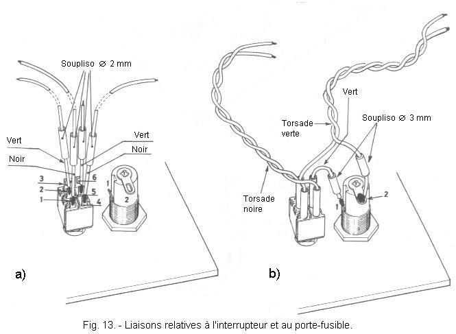
m) Prepare four pieces of soupliso of Ø 2 mm and two pieces of Ø 3 mm each about 1 cm by cutting them in the souplisos that you had in your possession.
n) Etam terminals 1, 2, 4 and 5 of the switch as well as the terminals of the fuse holder.
o) Take one of the pieces of black insulated wire previously prepared. Reduce the tinned end to 2 mm and weld it vertically to terminal 1 of the switch (Figure 13-a). Avoid that tin flows to the base of the bollard.
p) In the same way, solder the second black wire to terminal 4 and a green wire to terminal 2.
Also solder the remaining green wire to terminal 2 of the fuse holder.
q) Cut a piece of green flexible wire of 0.25 mm2 section and about 5 cm.
Etame both ends as before, then solder one of them to terminal 5 of the switch.
Make sure there are no short circuits on the 4 wired terminals of the switch.
nsert the four pieces of Ø 2 mm soupliso on the four wires wired on the switch and push them to the base of the welded terminals, covering the welds made.
r) Insert a piece of Ø 3 mm soupliso on the green wire wired to terminal 5 of the switch, then solder the same green wire to terminal 1 of the fuse holder.
Then cover the weld by sliding the piece of Ø 3 mm soupliso.
Put the second piece of soupliso on the green wire wired to terminal 2 of the fuse holder.
Twist the two green wires and the two black wires together (Figure 13-b).
Figure 14 shows you the underside of the metal panel (front panel) at this stage of the power supply assembly.
Prepare the controller for the resistance measurement and perform the measurements shown in the table in Figure 15.
This table shows you the ohmmeter connection points and the values you need to obtain.
Fig. 15. - Table for the power off control of the power supply
N°
POINTS OF CONNECTIONS OF THE OHMMETER
VALUES TO OBTAIN
1
Between the two ends of the red wire twist
Greater than 40 kW
(after a few seconds)
2
Between the black bush and the red bush
3 at 4 kW
With the switch in the OFF position
3
Between the two ends of the black twist
∞
4
Between the two ends of the green twist
∞
5
Between the two ends of the black twist and one end then the other of the green twist
∞
With the switch in the opposite position to that of OFF
6
Between the two ends of the black braid
∞
7
Between the two ends of the green braid
∞
8
Between the black wire connected to terminal 1 of the switch and the green wire connected to terminal 2 of the switch
0
9
Between the black wire connected to terminal 4 of the switch and the green wire connected to terminal 2 of the fuse holder
0
10
Between each end of the green wires and the black bushing
∞
You must find the values in this table. If not, you must check the wiring to discover the anomaly. Remember to check the fuse. When all the control is correct, you can continue editing.


 Mounting the Power Circuit on the front panel
 Click here for the next lesson or in the summary provided for this purpose.
 Haut de page
 Next Page