Use of a Controlled Oscillator to Realize a Simple game of Pile or Face :
5. - THIRD EXPERIENCE : MOUNTING A CONTROLLED OSCILLATOR (Return)
With this manipulation, you will check the operation of a controlled oscillator. This circuit generating a rectangular signal must be activated by a validation signal.
5. 1. - REALIZATION OF THE CIRCUIT
a) Unplug the power supply and remove from the array all components and links related to the previous experiment.
b) Insert on the matrix the integrated circuit MM 74C02 containing four NOR circuits. Also insert resistance R1 of 2.2 MΩ 1 / 4 W 5% (red - red - green - gold), resistor R2 of 470 kΩ 1 / 4 W 5% (yellow - purple - yellow - gold) and capacitor C1 of 0.1 µF as shown in Figure 12-a. Also set up the indicated links.
c) Set switch SW0 to position 0 so that the input of the circuit is brought to level L.
The circuit diagram of the realized circuit is shown in Figure 12-b.
5. 2. - OPERATING TEST
a) Connect the power supply : the circuit oscillates at a frequency of approximately 10 Hz and the LED L0 turns on and off at a rate of ten times per second.
If you do not get this result, check the mount.
b) Set switch SW0 to position 1. LED L0 stops blinking and stays on permanently. The circuit is blocked with an H state output.
c) Put switch SW0 back to position 0. The circuit resumes its oscillation at the same frequency.
d) Change the values of resistance R2 and capacitor C1. You notice that the frequency of the output signal of the oscillator may vary.
The approximate frequency of oscillation of the circuit is given by the following relation :
This simplified formula is valid for capacity values above 2 000 pF and for values of R1 much higher than those of R2.
Here is an example of application of the controlled oscillator.
6. - FOURTH EXPERIENCE : USE OF A CONTROLLED OSCILLATOR TO REALIZE A SIMPLE GAME OF FILE OR FACE
By slightly modifying the previous circuit and adding a rocker, you make a circuit that simulates the game of coin or face with a coin.
6. 1. - REALIZATION OF THE CIRCUIT
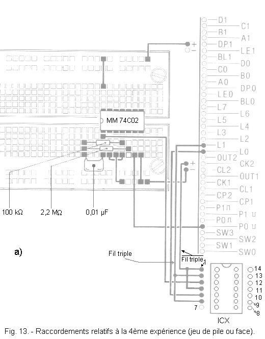
a) Disconnect the power supply. Replace the 0.1 µF C1 capacitor with another 0.01 µF capacitor and the 470 kΩ R2 resistor with another 100 kΩ (brown - black - yellow - gold).
b) Remove the connection between the pin 6 of the integrated circuit MM 74C02 and the switch SW0 and connect this pin 6 with the contact P0.
c) Also remove the connection between contact L0 and pin 1 of the integrated circuit MM 74C02 and connect this pin 1 to pin 3 of the ICX holder.
d) Insert into the ICX socket the integrated circuit MM 74C74 which contains two D flip-flops.
e) Make the ICX support links shown in Figure 13-a. The circuit diagram of the realized circuit is shown in Figure 13-b. You observe that the output of the oscillator is connected to the CLOCK input of the flip-flop. The
output of the flip-flop is connected to the DATA input of this same flip-flop.
As you saw in detail in the previous practices, with this assembly, at each clock face on the input CLOCK, the rocker changes state.
As soon as the clock signal stops, the rocker locks in the state where it is at that moment.
This montage simulates the game of coin or face in which a coin falls at random on one of its faces.
6. 2. - OPERATING TEST
a) Connect the power supply : one of the two LEDs (L0 or L1) lights up, the other one is off.
b) Press the P0 button : the circuit oscillates and both LEDs are lit. Indeed, the oscillation frequency is approximately 450 Hz and the eye can not perceive the successive ignitions and extinctions of the two LEDs.
c) Release P0 : one LED remains on, the other goes out.
You can not predict what the LED will stay on. It is therefore a result due to chance.
This is therefore a simple application of the controlled oscillator.
This type of oscillator finds other applications : for example to collect a periodic signal using a single pulse of more or less long duration. This is the case of a computer keyboard key that allows the repetition of a character.


 Oscillator Ordered to Perform a Single Game of Pile or Face
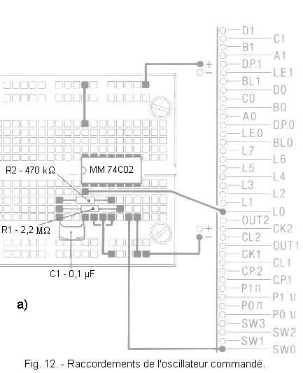
 Click here for the next lesson or in the summary provided for this purpose.
 Top of page
 Next Page