Examination of a Schmitt Flip-Flop and its Operation :
With this new practice, we will examine Schmitt scales and oscillators.
Schmitt's flip-flops are circuits that are widely used to reform poor quality signals, either because they are parasitic or because they have rising and falling edges that are too slow and therefore not very effective for controlling digital circuits.
Oscillators are circuits that generate cyclic signals. They are indispensable in the synchronized digital circuits to which they give the rate of operation so that some components, such as flip-flops, work synchronously.
We have seen that most scales have an input called CLOCK. By sending on this input the signal of an oscillator which is precisely called on this occasion CLOCK SIGNAL, the flip-flop is allowed to change state only in the presence of a pulse of this clock.
If, we send the same clock signal to the latches and circuit components having a CLOCK input, their operation will be synchronized, that is to say that all will change state at the same time.
1. - PREPARATION OF MATERIALS
In this practice, you will use the following materials :
1 resistance of 12 kW
1 / 4 W tolerance 5 % (brown - red - orange - gold)
1 resistance of 22 kW
1 / 4 W tolerance 5 % (red - red - orange - gold)
1 resistance of 15 kW
1 / 4 W tolerance 5 % (brown - green - orange - gold)
1 resistance of 100 kW
1 / 4 W tolerance 5 % (brown - black - yellow - gold)
1 resistance of 470 kW
1 / 4 W tolerance 5 % (yellow - purple - yellow - gold)
1 resistance of 2,2 MW
1 / 4 W tolerance 5 % (red - red - green - gold)
2 resistors of 1,5 MW
1 / 4 W tolerance 5 % (brown - green - green - gold)
3 resistors of 150 kW
1 / 4 W tolerance 5 % (brown - green - yellow - gold)
1 tantalum electrolytic capacitor of 0,33 µF - 10 V
1 tantalum electrolytic capacitor of 1 µF - 10 V
1 polyester capacitor of 0,1 µF
1 polyester capacitor of 0,01 µF
1 ceramic capacitor disc 330 pF
1 linear multiturn potentiometer of 10 kW
2 diodes 1N 4148
2 integrated circuits MM 74C14
1 integrated circuit MM 74C175
1 integrated circuit MM 74C02
1 integrated circuit MM 74C04
1 integrated circuit MM 74C74
1 braid of rigid wire isolated (red and black)
2. - FIRST EXPERIENCE : EXAMINING THE FUNCTIONING OF
A SCHMITT ROCKET
In this manipulation, you will first compare the operation of a circuit made with two inverters and the operation of a Schmitt rocker available as an integrated circuit.
2. 1. - REALIZATION OF THE CIRCUIT
a) Disconnect the power supply, remove the connections and components left on the matrix after previous experiments and remove the ICX Integrated Circuit.
b) Insert into the matrix the integrated circuit MM 74C04 containing six inverters, the multiturn potentiometer of 10 kΩ and the resistance of 22 kΩ 1 / 4 W 5% (red - red - orange - gold) in the position indicated in Figure 1-a ; then perform the links illustrated by this same Figure.
For the moment, do not put the 100 kΩ resistance in dotted line.
The diagram of the circuit thus produced is shown in Figure 1-b.
The input of the first INVERTER (pin 1) is connected to the potentiometer slider through the 22 kΩ resistor (R1).
This slider, by means of the adjustment screw, can be moved towards one end or the other of the potentiometer and thus to the ground or to the positive voltage of supply.
Thus, it is possible to apply to the input of the circuit a variable voltage continuously between zero volts and the supply voltage.
The output of the circuit (pin 4) is connected to LED L0.
2. 2. - OPERATING TEST
a) Connect the power supply.
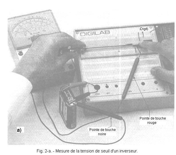
b) Connect the 10 volt DC voltage controlled controller between the ground (black tip) formed by the negative pole of the battery and the R1 terminal that is connected to the potentiometer slider (red tip) as shown in Figure 2-a.
In Figure 2-b, an enlargement shows you how to make this last link, using a piece of insulated rigid wire of appropriate length, one stripped end of which will be wound on the end of the red touch point and the other end inserted in the measuring point.
c) Hold the potentiometer firmly with one finger and with a screwdriver, turn the adjustment screw clockwise until the voltmeter reads zero volts (Figure 2-a). Under these conditions, the cursor is at the end of the race, towards the end connected to ground, and you notice that the LED L0 is off.
d) Now slowly turn the potentiometer screw counter-clockwise until the L0 LED lights up and note the voltage value indicated by the voltmeter on a piece of paper.
e) Continue turning the screw in the same direction until the voltage reading on the unit reaches the value of the supply voltage (+ 4.5V approx.), indicating that the slider has reached other end connected to the positive voltage. You notice that the LED L0 remains lit.
f) Turn the screw clockwise again to lower the circuit input voltage by stopping as soon as you see the LED go out and note the voltage reading read from the voltmete
You notice that this value coincides with the value measured in phase "d" when you turned the screw counter-clockwise and the LED was lit.
The voltage thus measured is called THRESHOLD VOLTAGE.
With this test, you have found that the threshold voltage for which the LED turns on or off as the input voltage is increased or decreased is about half of the supply voltage.
g)Now unplug
the power supply and insert on the matrix the resistance R2 of 100 kΩ 1 / 4 W 5% (brown - black - yellow - gold) shown in dotted line in Figure 1-a.
h) Connect the power supply again. Using the procedure described above, measure the values of the voltages corresponding to the switching on and off of the LED.
You notice that by increasing the input voltage of the circuit from 0 V, the LED lights up at a higher voltage value than previously measured. This new value is called TOP THRESHOLD. By then reducing the input voltage, you measure another threshold voltage value called LOWER THRESHOLD, corresponding to the extinction of the LED. By comparing the value of the upper threshold with that of the lower threshold, you can see that they are different.
With the values of the resistors used and for a supply voltage value of 4.5 V, the upper threshold is in fact about 2.8 V while the lower threshold is about 1.8 V.
This property of the circuit is designated by the term of HYSTERESIS ; the hysteresis difference, that is the difference between the two values of the upper and lower threshold voltages, is given by the product of the supply voltage and the ratio between the resistors R1 and R2 (Figure 1-b).
In our case, it is :
In conclusion, the experiment circuit is characterized by two switching thresholds, one valid when the input voltage increases and the other the input voltage decreases.
This property is very useful for signals disturbed by parasites.
Indeed, as soon as the input signal has crossed the upper threshold, the circuit switches and remains in this state as the input signal does not descend, below the level of the lower threshold as we have seen previously.
Thus, even if the input signal would be subject to significant fluctuations, the circuit would ignore them as long as the magnitude of these fluctuations is less than the hysteresis deviation, that is, the difference between the values of the two thresholds of the rocker.
In Figure 3, the behavior of this circuit, known as Schmitt Flip-flop or Schmitt trigger, is compared with that of a normal CMOS circuit.
In the case of the ordinary circuit, since the input voltage crosses the switching threshold several times, the output voltage undergoes as many changes of states.
On the contrary, the Schmitt trigger gives a signal which is not subject to the undesirable fluctuations which occur in the vicinity of the switching thresholds.
2. 3. - EXAMINATION OF THE INTEGRATED SCHMITT ROCKET MM 74C14
To have a Schmitt rocker, it is not necessary to resort to the circuit that you just realized. Indeed, this rocker is available as an integrated circuit.
A typical example is the integrated circuit MM 74C14 that you surely have in your possession and whose electrical diagram is shown in Figure 4.
As you can see, it includes six inverters, each of them having the characteristic of a Schmitt flip-flop.
Remember that this characteristic is specific to the inputs of the circuits and that the behavior of the inverters is identical to that of a normal inverter from the point of view of the operating table and the truth table.
To check the operation of the MM 74C14, proceed as follows :
a) Disconnect the power supply, remove the integrated circuit MM 74C04 from the matrix and replace it with the MM 74C14. Also remove the R2 resistance of 100 kΩ. Leave in place, however, the other components and connections.
So you simply replaced the normal inverters with Schmitt's flip-flops.
b) Connect the power supply and vary the input voltage of the first inverter by acting on the potentiometer.
You notice that the behavior of this new circuit is the same as that for the previous circuit when, with the insertion of the resistance of 100 kΩ, you obtained two different switching thresholds.
The two threshold values you have measured are those of the characteristics of the integrated circuit in question.
Apart from the one used, there are others commercially available, such as some NAND gates whose inputs have the characteristic characteristic of Schmitt's flip-flops.
3. - SECOND EXPERIENCE : USE OF A SCHMITT
ROCKET TO REALIZE AN OSCILLATOR
An oscillator is a circuit which has no stable state but which, as its name indicates, oscillates continuously between two so-called unstable states.
The number of oscillations that the circuit completes, in one second is the frequency, measured in Hertz (Hz). One Hertz equals one oscillation per second.
Oscillators are indispensable in all synchronized digital circuits in which the different components work synchronously (that is to say, change state or switch at a specific moment controlled by a clock signal generated by a single oscillator).
During this manipulation, you will examine a very simple oscillator, but nevertheless effective, which will then permanently mounted on the printed circuit of the digilab and will be a very useful signal generator.
3. 1. - REALIZATION OF THE CIRCUIT
a) Disconnect the power supply and remove all components and connections from the circuit previously experienced, but leave the integrated circuit MM 74C14 in place.
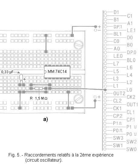
b) Introduce on the matrix the resistance R of 1.5 MΩ - 1 / 4 W - 5% (brown - green - green - gold) and the tantalum electrolytic capacitor (C) of 0.33 µF - 10 V (in respecting the polarities of its terminals) at the locations shown in Figure 5-a which also illustrates the connections to be made. The circuit diagram of the circuit thus produced is shown in Figure 5-b.
3. 2. - OPERATING TEST
a) Connect the power supply and observe the LED L0 : you notice that it turns on and off periodically about once a second. This means that the output voltage switches alternately from a level L to a level H and vice versa, which determines the switching on and off of the LED.
In this case too, as for the monostable, circuit operation is based on charging and discharging the capacitor through the resistor.
On power-up, the capacitor C is discharged, so the input of the inverter is at the level L. The output therefore goes to the level H. Then the capacitor starts to charge through the resistor R. After a time t depending on the time constant RC according to the relation t = RC, the voltage across the capacitor has reached a value such that it exceeds the upper switching threshold of the flip-flop and thus the output goes to state L. As a result, the capacitor begins to discharge through the resistor.
When the voltage across C reaches the lower threshold, the flip-flop switches again, returning to the initial conditions since the output is now at level H and thus C begins charging.
The charging and discharging of the capacitor is repeated periodically in the manner described, so the flip-flop continuously switches from one state to another, generating an output voltage which looks like a rectangular signal, as shown in Figure 6. In our case, with R = 1.5 MΩ and C = 0.33 µF,the capacitor charge and discharge time is :
t = R x C = 1.5 x 106 x 0.33 x 10-6 = 0.495 s or about a 1 / 2 seconds.
Since the circuit switches every 1 / 2 second, it takes a full second for the output voltage to complete a complete cycle.
The time required for the voltage to complete a complete cycle is called PERIOD and is designated by the letter T.
In our case, we have T = 2t = 2 R x C
The shorter the period, the greater the number of complete cycles that the output voltage can accomplish in one second.
The number of cycles per second, that is to say the frequency, is given by the ratio :
which is written symbolically :
with f
expressed in Hertz and T in seconds.
In our case, replacing T by its value of 1 s, we obtain :
b) Disconnect the power supply, replace the 1.5 MΩ resistor with another 470 kΩ 1 / 4 W 5% (yellow - purple - yellow - gold) and reconnect the power supply.
You notice that the LED turns on and off at a frequency three times higher than that of the previous case.
Indeed, the period of the oscillation produced by the circuit is equal to :
T = 2 RC = 2 x 470 x 103 x 0,33 x 10-6 = 0,31 s
We deduce the frequency of the generated signal :
c) Disconnecting the power supply each time, replace the resistor or capacitor with other components with lower and lower values.
You observe that the frequency of the oscillation increases more and more, until the LED remains lit permanently.
This does not mean that the oscillator does not work, but simply that the LED lighting and extinguishing phases occur so quickly that the eye is no longer able to appreciate them.


 Examination of a Schmitt Toggle
.jpg)
.gif)
.jpg)


 Click here for the next lesson or in the summary provided for this purpose.
 Top of page
 Next Page