The true monostable studied in the previous experiment was performed with a D rocker. There are, however, integrated circuits designed specifically to operate as monostable under optimal conditions. Here you use the MM 74C221. This integrated circuit contains two independent monostables. The representation is given in Figure 6-a.
It is necessary to add an external resistor and capacitor to the integrated circuit to operate the monostable.
The pins to which these two components are connected are indicated by R / C ext and C ext indicated in Figure 6.
The monostables being two in number, the pins of the first carry the index 1, those of the second the index 2.
The terminals C ext and R / C ext relating to the first monostable are indicated by 1 C ext and 1 R / C ext ; those relating to the second by 2 C ext and 2 R / C ext.
The duration T of the output pulse of the monostable, measured in seconds is equal to the product of Rext, expressed in megohm and Cext expressed in microfarad.
By connecting a resistance of 1 MΩ and a capacitor of 1 µF, the pulse will have a duration of 1 second. The monostable has two main inputs A and B, a CLR entry (abbreviation of CLEAR) ; and two outputs Q and .
5. 1. - REALIZATION OF THE CIRCUIT
a) Disconnect the power supply and remove all components and connections made during the previous experiment.
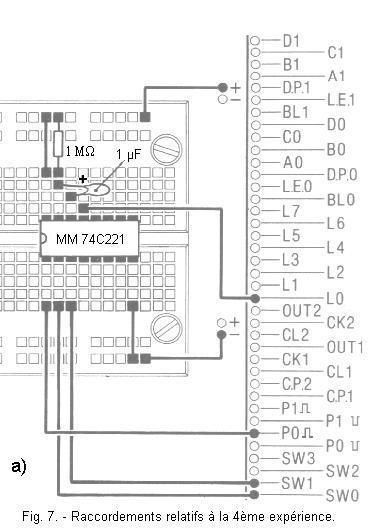
b) Carry out the assembly shown in Figure 7-a respecting the orientation of the integrated circuit and the polarities of the tantalum capacitor.
c) Keep the integrated circuit MM 74C00 in position IC1 (anti-rebound).
The circuit diagram is shown in Figure 7-b. You notice that the second monostable is not used.
Input 1A is connected to contact P0,
input 1B to switch SW0 and input CLR to switch SW1.
Output 1Q controls LED L0.
5. 2. - OPERATING TEST
a) Connect the power supply, LED L0 is off. It can light for a short time. Indeed, the monostable is in a stable state which corresponds to a level L for the output Q.
b) Press and release the P0 button. LED L0 lights for 1 second.
c) Now, press P0 and hold it in this position : L0 remains off.
d) Release P0 : L0 lights for 1 second. So you see that it is by releasing the P0 button that the monostable triggers and delivers a pulse output. This monostable is triggered by a falling edge applied to the input A.
e) Now put SW0 on position 0. Input B is on a level L.
f) Press and release P0. LED L0 does not light up. Input B is therefore a validation input. The monostable can be triggered only if this B input is at a level H.
g) Now, interchange the links relating to the two inputs A and B. The input A is connected to SW0, the entry B to P0.
h) With SW0 on the position 0, you impose the state L on the entry A.
i) Press and release the P0 button : The L0 LED lights for 1 second.
j) Put SW0 on position 1, input A is in state H. Operate P0. LED L0 remains off.
The functions of inputs A and B are now reversed : Input A has become the validation input and Input B is controlling the monostable.
You can now check whether a rising edge or a falling edge is applied to input B to control the monostable.
k) To do this, press P0 and hold it for a while in this position, then release it. You observe if the L0 LED lights up by pressing or releasing P0. Refer to the operating table in Figure 8. It is a rising edge applied at B that triggers the monostable.
It remains to examine the operation of the CLR input.
l) Press P0, LED L0 lights up, immediately switch SW1 to 0 and return it to 1.
For a short time, you apply a level L to the CLR input.
You notice that the L0 LED goes out before the 1 second pulse duration has elapsed.
You can also increase the value of R and C. The CLR entry is the priority reset entry. It can be activated at any time by a level L.
m) Check the variations of
by connecting the pin 4 of the integrated circuit to the LED L1 and by repeating the previous tests.
All these results are recorded in the operating table.
In this table, the arrow
indicates a positive transition from the low state to the high state ; the arrow
indicates a negative transition. The symbol "X" in this table indicates that the logical state can be indifferently 0 or 1.
6. - FIFTH EXPERIENCE : USE OF DOUBLE MONOSTABLE
MM 74C221
IN A CIRCUIT CONTROLLER OF REFLEXES
As an example of application of the integrated circuit MM 74C221, you will now realize a circuit with which it is possible to check the speed of reflexes and to have the notion of the time that passes.
6. 1. - REALIZATION OF THE CIRCUIT
a) Disconnect the power supply and remove only the connections for the last completed circuit and leave the components in place.
b) Insert an integrated circuit MM 74C74 into the ICX holder.
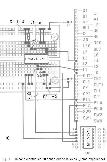
c) Make the connections shown in Figure 9-a also showing the location where two other components should be inserted : a 1 MΩ resistor and a 1 µF capacitor forming the RC cell for the second monostable of the MM 74C221.
When inserting the capacitor, observe the polarities of the terminals referring to Figure 9-a.
d) Set switch SW0 to position 1.
You thus realize the circuit represented by the diagram of Figure 9-b. As you can see, the two monostables are connected one after the other ; the first monostable is controlled by the P1 button.
The flip-flop D has its input DATA connected to the output Q of the second monostable and receives on its input CLOCK the control signal of the button P0 ; the SW0 switch, connected to the CLEAR input, resets the flip-flop if it is set to 0.
The signals present at the Q outputs of the two monostables and the flip-flop D are displayed by means of the LEDs L4, L1 and L0.
6. 2. - OPERATING TESTS
a) Connect the power supply and observe LEDs L1 and L4.
You notice that they are off or stay on for a brief moment, while the L0 LED is probably on.
In this case, reset the scale by temporarily setting SW0 to position 0 and return it to position 1. Now the circuit is ready for operation.
b) Press and release the pushbutton P1.
The L4 LED lights up as soon as the button is released and stays on for about 1 second. Immediately after, as soon as L4 goes out, L1 also lights up for 1 second.
If the circuit does not work as expected, carefully check the connections and insertion of the integrated circuits and components.
c) Press P1 again and while L1 is lit, press P0. LED L0 lights up and stays on even after L1 has been switched off.
The purpose of this editing is to check the speed of reflexes : it is to press P0 during the brief moment when L1 is lit. If you press during this time, L0 lights up and attests to the correct result of the test. Otherwise, it stays off.
The first monostable is used to run a sufficient time between the pressure of P1 and the moment when it is necessary to press P0. Naturally, with the LEDs remaining lit for 1 second, the game is rather easy. To make it more difficult, it is enough to reduce the lighting time of L1.
d) To do this, disconnect the power supply and remove the resistor R2 of value 1 MΩ connected between pin 7 of the MM 74C221 and the positive voltage and replace it with a resistor of 470 kΩ.
e) Connect the power supply, reset the scale by pressing SW0 and repeat the experiment.
You observe that L1 remains on for a shorter time : approximately 1 / 2 seconds instead of 1 second which makes it more difficult to light L0 the first time.
By further decreasing the value of R2, you make the game even more difficult ; for example, taking R2 = 330 kΩ, the useful time to press P0 becomes equal to 1 / 3 s, the value close to the limit of the minimum human reaction time.
Another way to make the game more difficult is to disconnect the LED L4 so as not to have the indication that precedes the ignition of L1. One can also change the value R1 to vary the moment when L1 turns on. By using the resistors and capacitors at your disposal, you can get different combinations of the delay with which L1 turns on and how long it stays on. This makes reflex control very easy or very difficult.


 Using the Integrated Circuit MM 74C221 in a Reflex Controller Circuit
 Click here for the next lesson or in the summary provided for this purpose.
 Top of page
 Next Page