Before you start editing, it is necessary to prepare the series of connectors with a precise number of contacts by properly splitting the two 32-pin connectors that you have purchased or already have.
For this purpose, it is sufficient to use a sharp knife practicing in the manner illustrated in Figure 9-a.
Take one of the two connectors and place it on your work table ; insert the blade of the knife in the notch of separation between the twentieth and the twenty-first contact, then firmly holding the handle of the knife pressed on the table (make sure that you are at the right place), put pressure on the blade so as to make a clean cut in the insulating support of the connector.
Using this method, taking care to count the number of contacts each time, make three more cuts at the points shown in Figure 9-b. You will thus obtain the first four connectors having respectively 20, 7, 3, 2 contacts. Put them carefully aside so you do not lose them.
At the end of this operation, nine connectors are available as shown in photo 9-d.
In the event of a cutting error, it is always possible to complete the missing contacts by taking the necessary additional contacts on a strip. At the time of the wiring, it is necessary in this case to put side by side the appropriate number of contacts to obtain a complete connector.
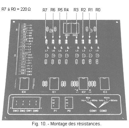
You can now start the work, by performing on the printed circuit the establishment of the resistances of R0 to R7. Proceed as follows :
Take the resistance R0 of 220 Ω - 1 / 4 W tolerance ± 5% (red - red - brown - gold) and after properly bending the connections, place it on the circuit board, in the location shown in Figure 10.
To do a good job, be sure to bend the two connections at the correct distance and at a right angle so that the body of the resistor is centered in relation to the holes provided on the Printed Circuit Board, as shown in figure 11-b. If the bending distance of the terminals is insufficient (Figure 11-a) or excessive (Figure 11-c), the resistor can not rest against the wafer.
In such cases, it is necessary to correct the bending of the terminals by proceeding gently with a clamp without exerting stress on the body of the component :
turn the circuit back while holding the resistor tight against it, spread the connections slightly so that it stays in place. Make the soldering of its connections and cut the ends that exceed.
follow the same procedure and solder to their respective locations on the Printed Circuit Board, resistors R1, R2, R3, R4, R5, R6, R7, all of 220 Ω - 1 / 4 W tolerances ± 5% (red - red - brown - gold).
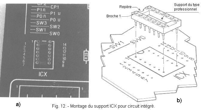
You will now mount the supports for integrated circuits :
take a professional 14-pin stand, first make sure all pins are straight : if one is not, straighten it carefully with a pair of pliers tweezers. Insert the support in the holes provided on the printed circuit and marked by the symbol ICX (Figure 12-a) by positioning it so that the pin 1 (recognizable by the mark) coincides with the hole designated by the number 1 on the printed circuit board (Figure 12-b).
hold the holder with a finger, in contact with the printed circuit, then turn it over and make sure that the 14 pins protrude sufficiently to be able to weld them correctly (Figure 13-a).
Figure 13-b shows a limiting case where a pin has folded under the support during its insertion on the circuit. We must avoid this pitfall, because the pin may break by straightening. Then solder the support :
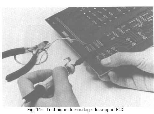
making sure that all pins stand out sufficiently on the copper tracks side and continuing to hold the plated support to the circuit, secure with two light spots solder pins 7 and 14, as shown in Figure 14 ; now the support can not fall anymore.
Now, put the circuit board on the worktable and make very careful the soldering of all the other pins of the support and to finish, take again the two welds of the pins 7 and 14.
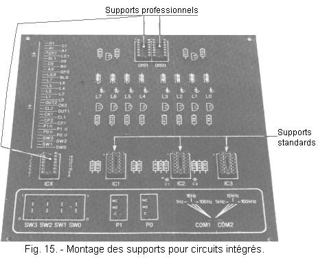
following the same procedure as for welding the ICX support, insert and solder the other two professional supports in their respective locations on the printed circuit, and marked with DIS 0 and DIS 1.
always using the same technique, weld the three standard supports IC1, IC2, IC3 as shown in Figure 15.
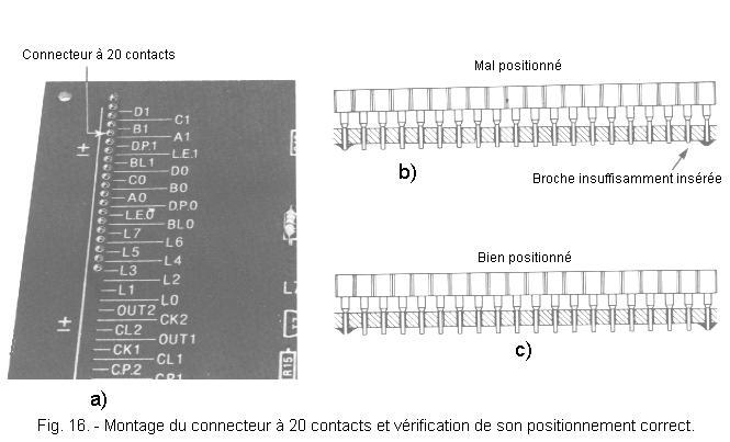
Now take the 20-pin connector and insert it into the holes marked D1 through L2 as shown in Figure 16-a. Placing the connector firmly against the circuit board, turn the circuit board over and secure the first and twentieth pins of the connector.
Return the circuit again and make sure that the connector is correctly positioned, as shown in Figure 16-c.
In the case where one of its ends does not adhere well to the circuit, see Figure 16-b, it is enough to heat the welding which prevents the pin from penetrating sufficiently, while exerting a slight pressure with the finger for the to penetrate thoroughly.
After the correct insertion of the connector, you can proceed to the soldering of the remaining pins and remake lastly those of the pins 1 and 20.
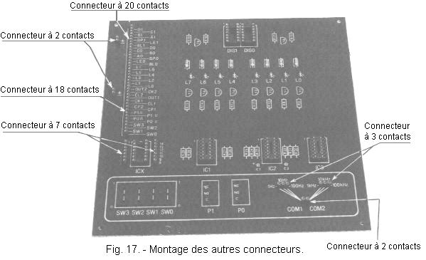
Using the same method, mount the following connectors, referring to Figure 17 :
take the 18-way connector and insert its pins into the holes from L1 to SW0 ; position it and solder it as you did for the previous one.
mount and solder two 2-way connectors in the marked (+) and (-) holes.
mount and solder the two 3 - pin connectors in the corresponding holes labeled "1 Hz - 10 Hz - 100 Hz" and "1 kHz - 10 kHz - 100 kHz".
mount and solder the last 2-pin connector in the holes labeled COM1 and COM2.
mount and solder the two 7-pin connectors on each side of the ICX Bracket.
Now you have to prepare two pieces of soft wire, one red and the other black, with alligator clip on the end. They will temporarily serve to supply the circuit board with a 4.5 V battery ; thereafter you will have the opportunity to realize the definitive stabilized power supply :
Take the piece of soft red wire about 25 cm, strip and tin both ends 3 to 5 mm and then weld one of them to a crocodile clip. To easily perform this operation, the clip should be attached to a piece of cardboard to hold it as shown in Figure 18-a.
thread the red insulating cap onto the crocodile clip as shown in Figure 18-b.
take the piece of black flexible wire about 25 cm, strip and tin both ends 3 to 5 mm, then weld one of them to the other crocodile clip.
Then thread the black insulating cap onto the crocodile clip as before.
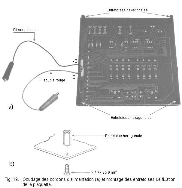
weld the free end of the red flexible wire to the copper strip marked + B on the underside of the PCB (copper-side) as shown in Figure 19-a.
Weld the free end of the black flexible wire to the copper strip marked - b on the underside of the printed circuit (copper-side), also shown in Figure 19-a.
Mount the four hexagonal spacers on the copper tracks side in the four holes at the corners of the PCB. Block them without forcing with the Ø 3
x 6 mm, screws, as you can see in detail in Figure 19-b.
As a general rule, in electronics, two types of checks are always carried out : off-line or cold-on checks and undervoltage checks to first check the conformity of the wiring and then to take measurements with regard to the following : the most important or characteristic voltages.


 Footer
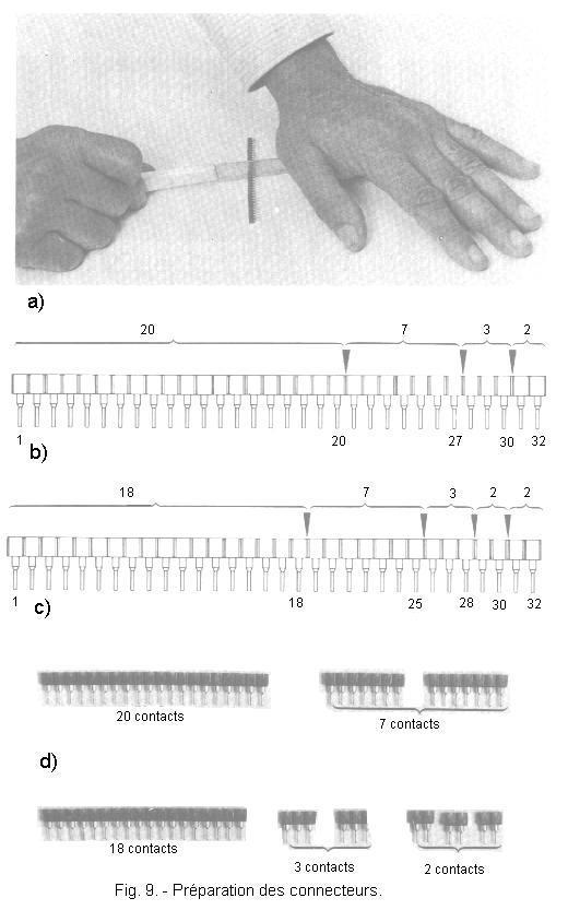
 Click here for the next lesson or in the summary provided for this purpose.
 Top of page
 Next Page