Digital / Analog Converter for Generating a Triangular Signal :
4. - THIRD EXPERIENCE : USING OF DIGITAL / ANALOG CONVERTER TO GENERATE AN TRIANGULAR SIGNAL
The applications of the D / A converters are numerous, for example it is possible to use them to generate signals of very diverse shapes. Just send a sequence of appropriate numbers on the input.
Many control circuits for industrial processes, as well as telephony and digital recording are based on this principle.
A spectacular application is the generation of sound signals. Virtually all electronic musical instruments are made using digital circuits and usually controlled by a microprocessor.
With this experiment, you will generate a triangular signal and reproduce the corresponding sound using the speaker.
4. 1. - REALIZATION OF THE CIRCUIT
a) Keep all the previous assembly (the components remain in their place) by eliminating only the connections between the four input resistors R1, R2, R3 and R4 and the four contacts SW0, SW1, SW2 and SW3.
b) Insert on the matrix the integrated circuits MM 74C193 (synchronous up / down counter), MM 74C154 (4 ways decoder to 16), MM 74C74 (double D Toggle) and MM 74C00 (4 NAND doors) by arranging them as indicated Figure 10-a.
c) Make the connections indicated in this same figure.
The electrical diagram of the realized circuit is given in Figure 10-b.
4. 2. - OPERATING TEST
a) Put SW0 on position 1.
b) Connect the battery and turn on the digilab.
The display DIS0 indicates 0 because the CLEAR input of the counter is activated.
c) Put SW0 on the 0 position.
d) Press and release the push-button P0, the counter increments from 0 to F or decrements from F to 0 according to the logic state of the flip-flop MM 74C74. If its output Q is in state 1, the counter increments, if it is at 0, the counter decrements.
e) Using the
controller,
check the output voltage of the converter. When the counter increments from 0 to F, the voltage varies from 0 volts to + 3.75 volts, as shown in the table of the previous experiment. When the counter decrements from F to 0, the voltage varies from + 3.75 volts to 0 volts.
f) Disconnect the battery and turn off the digilab.
You will now modify the circuit for automatic operation.
g) Remove the connection between pin 4 of the integrated circuit MM 74C00 and the contact P0.
h) Connect pin 4 of circuit MM 74C00 to contact CP2.
i) Arrange the clock generator at 10 kHz.
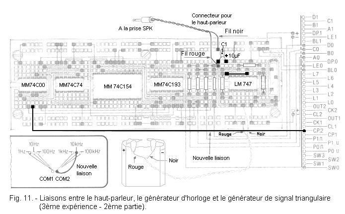
j) Insert on the matrix the capacitor C1 of 10 µF in the position indicated Figure 11. The terminal + of C1 will be connected to the pin 10 of the LM 747.
k) Connect the digilab loudspeaker to the triangular signal generator using the connector with the jack. The red wire is connected to the negative terminal of C1 and the black wire is connected to ground.
l) Set SW0 to position 1.
m) Connect the battery and turn on the digilab.
n) Put SW0 on the position 0.
You hear a sound coming from the speaker.
c) Turn off the digilab and unplug the battery.
The rate of the voltage of Figure 12 is that which is obtained at the output of the triangular signal generator in the absence of the loudspeaker.
This is a staircase function. The number of "steps" corresponds to the resolution of the digital / analog converter.
When the speaker is connected, the signal at the output of the converter is impaired due to the low impedance of the speaker.
Referring tothe circuit diagram of Figure 10-b and the corresponding block diagram of Figure 13, the operation of the circuit can be described as follows.
The counter increments to 15 ; at this time, the output 15 of the decoder goes to the level L and through the NAND gate C, the flip-flop (wired in Toggle mode) changes state because a positive edge is applied on its input CLOCK.
The clock pulses, which previously reached the COUNT UP input, now reach the COUNT DOWN input of the counter.
When the output of the counter reaches the state 0, the output 0 of the decoder goes to the level L, which makes change again the state flip-flop.
The clock signal returns to the COUNT UP input and a new cycle begins.
It takes 32 clock pulses to determine a complete period of the triangular signal.
Indeed, there are 16 pulses for the incrementation of the counter and 16 pulses for its decrementation.
The frequency of the triangular signal is therefore :
10 kHz / 32 = 312,5 Hz
The two outputs 0 and 15 of the decoder arrive on the NAND gate C. As soon as one of these outputs passes on the level H at the level L, there is a clock pulse on the rocker wired in divider by 2.
The two NAND gates A and B constitute a demultiplexer that sends the clock signal, either to the COUNT UP input or to the COUNT DOWN input.
It is possible to generate a different signal by modifying the editing somewhat.
For example, by changing the value one or more resistors R1, R2, R3 and R4, one can obtain a much less uniform signal than that obtained previously.
It is also possible to wire a capacitor in parallel on R7 and P as shown in Figure 14-a. The triangular signal is filtered by the capacitor (Figure 14-b) and becomes substantially sinusoidal.
It is also possible to change the frequency of the triangular signal.
Simply change the frequency of the clock signal.
By finally modifying the circuit as shown in Figure 15, you can generate a semi-triangular signal.
To do this, simply connect the COUNT DOWN input to the (+) and send the clock signal directly to the counter's COUNT UP input. The decoder and the demultiplexer are no longer needed.


 Footer
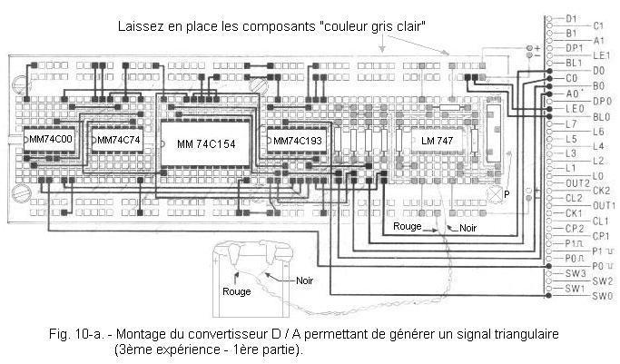
 Click here for the next lesson or in the summary provided for this purpose.
 Top of page
 Next Page