Examining a Circuit performing the Sum of two 1 bit Numbers :
In this practice, we will examine the following digital circuits : summators, multiplexers, and demultiplexers.
1. - RECALLS AND PREPARATION OF HARDWARE
1. 1. - REMINDERS
Summators are more or less complex circuits that perform the addition of numbers expressed in binary code.
We will examine the half-adders, the complete summers and we will analyze the serial sum method and the sum-in-parallel method.
Multiplexers are electronic switches that allow multiple lines to be routed to one, while demultiplexers provide the reverse function.
We will finally see how a multiplexer can also be used to replace a door network.
Before starting to examine these circuits, it is useful to remember the rules that govern the sum of bit numbers of a bit. These are summarized in the table of Figure 1 where A and B are the terms of the sum, S the sum and C the restraint.
When adding binary numbers, the holdback from the partial sum of lower order bits (digits) must be taken into account. Figure 2 shows the results with holdings of the sum of two bits.
In this table, A and B are the terms, Ci the carry from the previous partial sum, S the sum and Ci + 1 the carry.
1. 2. - PREPARATION OF HARDWARE
MM 74C86
MM 74C08
MM 74C32
MM 74C00
MM 74C164
MM 74C165
MM 74C74
MM 74C02
MM 74C83
MM 74C151
MM 74C154
MM 74C163
Remember that integrated circuits must be separated from their antistatic foam only before their immediate use and must always be put back on their foam after use.
2. - FIRST EXPERIENCE : EXAMINATION
OF A CIRCUIT PERFORMING THE SUM OF TWO NUMBERS OF 1 BIT
The Figure 3 gives a simple graphical representation of the summing circuit that you are going to experiment now.
The two binary numbers of 1 bit to be added are applied to the inputs A and B and the sum of these is obtained at the output S according to the rules of the bit sum reported hereinafter.
0 + 0 = 0
with restraint = 0
0 + 1 = 1
with restraint = 0
1 + 0 = 1
with restraint = 0
1 + 1 = 0
with restraint = 1
To perform this function, one of the exclusive OR gates of the integrated circuit MM 74C86 will be used ; his operating table that you know is this :
2. 1. - REALIZATION OF THE CIRCUIT
a) Remove from the matrix and ICX support all the connections and components related to the last experiment.
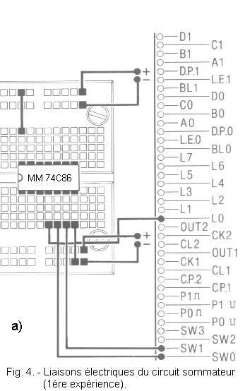
b) Insert on the matrix the integrated circuit MM 74C86 (4 OR Exclusive) and make the connections illustrated in Figure 4-a. The electrical diagram of the realized circuit is given in Figure 4-b. As you can see, only one Exclusive OR gate is used. The inputs are connected to switches SW0 and SW1, while the output is connected to LED L0.
Thus, at the inputs A and B of the circuit is applied a low level (L) or high (H) depending on whether the corresponding switches SW0 and SW1 are switched to the position 0 or the position 1.
LED L0 indicates the level of the output.
2. 2. - OPERATING TESTS
a) Insert the plug into the mains socket.
b) Set both SW0 and SW1 to the 0 position and turn on the Digilab.
Associate at the low level (L) the binary digit 0 is at the high level (H) the binary digit 1.
Thus, in the present case, at the inputs A and B are two binary numbers of 1 bit, each of them being equal to 0.
Observe the LED L0 : it is off. This indicates that the output (S) of the Exclusive OR is low, so that the output binary digit is 0.
The first rule of the binary sum 0 + 0 = 0 is thus confirmed.
c) Now put SW0 on position 0 and SW1 on position 1 : thus on entry A is present bit 0 and on entry B on bit 1.
For the second rule of the binary sum 0 + 1 = 1 to be satisfied, the output of the summator must indicate 1 as the result, ie it must be at the high level ; for confirmation, observe L0, it must be on.
d) Now check the third rule 1 + 0 = 1 by setting SW0 to 1 and SW1 to 0.
In this case too, L0 should light up.
e) Finally check the last rule 1 + 1 = 0 with hold of 1 by setting SW0 and SW1 both to 1.
In this case, L0 must be extinguished, however the restraint is not indicated.
f) With this experiment completed, turn off the Digilab.
In summary, this manipulation allowed you to see that a single OR Exclusive gate can sum two binary numbers by 1 bit.
However, it remains to indicate the restraint. Indeed, in the case of the sum 1 + 1, the circuit gives the exact sum which is well 0, but not the hold which is worth 1.
It is therefore necessary to add to the preceding circuit a circuit which performs the computation of the restraint.
In the next experiment, you will wire a circuit that generates this restraint.
3. - SECOND EXPERIENCE : TESTS OF OPERATION OF A SUMMER OF A BIT WITH RETENTION
In this experiment, you will realize a summator more complete than the previous one because it indicates the value of the restraint.
This summator thus has two entries to which are applied the two numbers to add and two outputs : one to indicate the result of the sum and the other to indicate the retention, as shown in Figure 5.
The output indicating the restraint is identified by the letter C which is the initial of the English term CARRY.
3. 1. - REALIZATION OF THE CIRCUIT
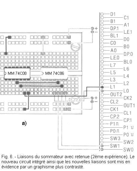
Leave the assembly of the previous experiment in place, insert on the matrix the integrated circuit MM 74C08 (quadruple AND) and make the new links highlighted in Figure 6-a.
The electrical diagram of the realized circuit is given in Figure 6-b.
3. 2. - OPERATING TESTS
a) Place SW0 and SW1 on the 0 position.
b) Turn on the Digilab. Under these conditions, the following sum is :
0 + 0 = 0
with restraint = 0
Thus, L0 which indicates the sum and L1 which indicates the restraint are extinguished.
c) By correctly positioning SW0 and SW1, check the following amounts :
0 + 1 = 1
with restraint=
0
1 + 0 = 1
with restraint =
0
d) Finally, set SW0 and SW1 to position 1 : L1 lights up.
Indeed, you have just checked the binary sum :
1 + 1 = 0
(L0 off) with restraint = 1
(L1 on),
which can be written in the form :
1 + 1 = 102
The same amount in decimal code becomes 1 + 1 = 2.
e) With the experiment complete, turn off the Digilab. The circuit under consideration is called half-adder because it does not take into account the restraint coming from a possible previous summing circuit.
In the following experiments, you will examine circuits that do not have this limitation and are therefore called complete summers.
In addition, you will realize more complex circuits that allow to add numbers composed of several binary digits.


 Examining a circuit performing the sum of two 1 bit numbers
 Click here for the next lesson or in the summary provided for this purpose.
 Top of page
 Next Page