4. - SECOND EXPERIMENT : OPERATION OF THE DECODER MM 74C154
The use of a decoder may be necessary to facilitate the understanding of the coded information.
Indeed, we are used to using a decimal representation and not the binary code, much more tedious to use because of the high number of digits 0 and 1.
In this experiment, as well as in the following, you will learn how to use a decoder to translate the binary code of a 4 bits number into a decimal representation of this more explicit number.
This decoder can be useful, for example, to immediately know the status of a modulo 16 counter.
The integrated circuit MM 74C154 allows this decoding.
It has 4 main entries which correspond to the 4 bits of the binary number to be decoded and 16 outputs.
The output corresponding to the binary number present on the inputs is at the level L, the other outputs being at the level H.
If the 16 outputs are connected to 16 LEDs, it is possible to immediately know the binary number present at the input of the decoder.
The logic diagram and the assignment of this decoder are respectively reported in Figure 5-a and 5-b.
As can be seen in Figure 5-a, this decoder consists solely of a network of logic gates.
The binary number to be decoded is applied to the entries A, B, C and D (see Figure 5-b).
The two inputs G1 and G2 are called STROBE. These are two decoder validation inputs. This is validated if these two entries are at level L.
Only one of the two is at level H for the decoder to be blocked.
In this case, the 16 outputs remain at level H which is the decoder's rest level.
As soon as the decoder is enabled, one of the 16 outputs goes to level L, which is the active level.
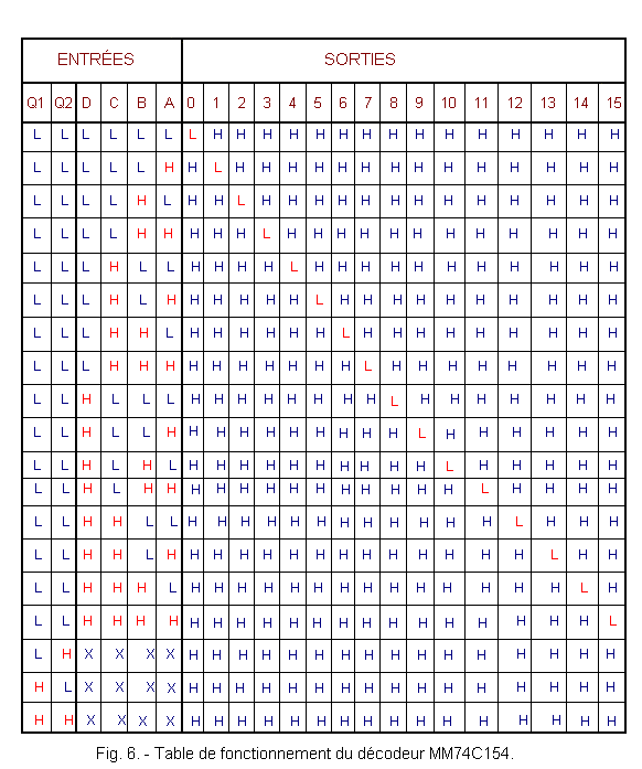
The operating table located in Figure 6 clearly shows that if at least one of the two enable inputs (G1 or G2) is at the H level, all 16 outputs are at the H level.
Remember that the symbol X in the operating table means that the logic level applied to the input has no influence on the state of the outputs.
4. 1. - REALIZATION OF THE CIRCUIT
a) Leave in place the links and the integrated circuit related to the previous experiment.
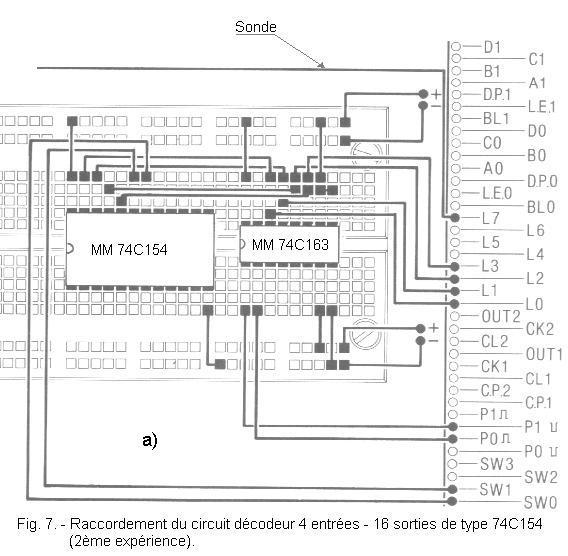
Insert the integrated circuit MM 74C154 on the matrix and make the connections indicated in Figure 7-a.
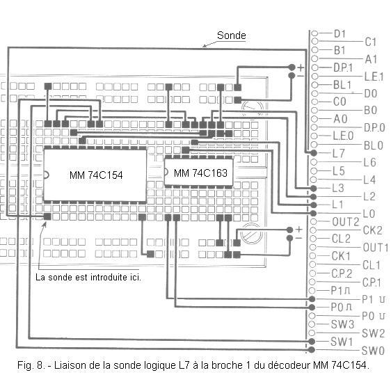
b) Insert the end of a piece of wire approximately 20 cm long into contact L7 of the connector group. Leave the other end free for now.
During the experiment, it will be connected in turn to the outputs of the decoder, by introducing it into the holes of the matrix corresponding to the outputs.
LED L7 is used as a logic probe.
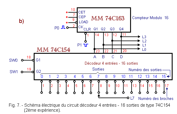
The circuit diagram of the assembly is shown in Figure 7-b.
4. 2. - OPERATING TEST
a) Turn on the digilab.
b) Press P1 and then P0 by briefly pressing both buttons.
The counter is reset.
The four LEDs L0, L1, L2 and L3 are off.
c) Release both P0 and P1 buttons.
Set the two switches SW0 and SW1 to position 0 (G1 and G2 are at level L). The decoder is thus validated.
d) Insert the free end of the conductor (probe) connected to L7 into the hole of the matrix that corresponds to pin 1 of the decoder.
Figure 8 shows you the link to perform.
Output 0 (pin 1) is at level L (LED L7 off).
Indeed, as you did just before a reset, the output 0 of the decoder is at level L.
e) Disconnect the probe from pin 1 and check, by connecting it to pins 2, 3, 4, 5, 6, 7, 8, 9, 10, 11, 12, 13, 14, 15, 16 and 17 decoder, that all these outputs are at level H.
LED L7 lights up as soon as the sensor is connected to one of these 15 outputs.
f) Press P0 once. The counter is incremented by one.
LED L0 lights up.
With the probe, you see that only output 1 (pin 2) is at level L.
g) Continue the experiment by incrementing the counter by one unit each time (using the P0 button).
Check that only the decoder output corresponding to the counter status is at level L.
h) Put SW0 on position 1.
All outputs are at level H. You can check it with the probe.
Then put SW1 on position 1, then bring SW0 back to position 0.
You can see that the outputs have remained at level H.
With this test, you have verified that only one of the two inputs G1 or G2 is at level H for the decoder to be blocked.
i) Turn off the digilab.
With this assembly, it would be enough to have at your disposal 16 indicator LEDs to know at any time the state of the meter.
Elevators have a signage that displays their position according to the floor they are on. These signals are made by means of a counter similar to that described here.
If the outputs of the decoder are active at the level L and not at the level H, it is because in general, a decoder is connected to another logic circuit whose inputs are active at the level L.
A typical case is provided by the counter MM 74C163 which, to be loaded, requires a level L on the LOAD input.
In this same decoder, the validation inputs G1 and G2 are also active at the level L.
This is useful when decoding binary numbers of more than four bits.
Indeed, these entries are used to invalidate one or more decoders.


 Footer
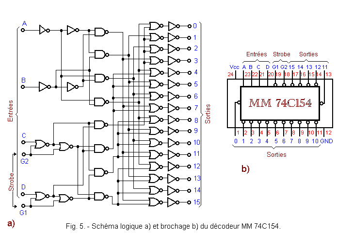
 Click here for the next lesson or in the summary provided for this purpose
 Top of page
 Next Page