 Monostable Redeclenchable Monostable Redeclenchable |
 Footer Footer |
The Real Monostables - Monostable Redeclenchable :
1. 3. 2. - THE REAL MONOSTABLES
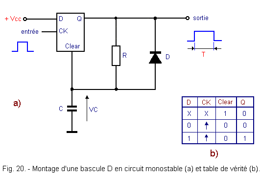
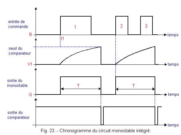
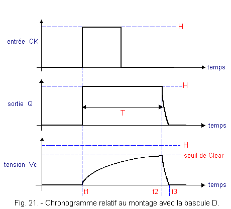
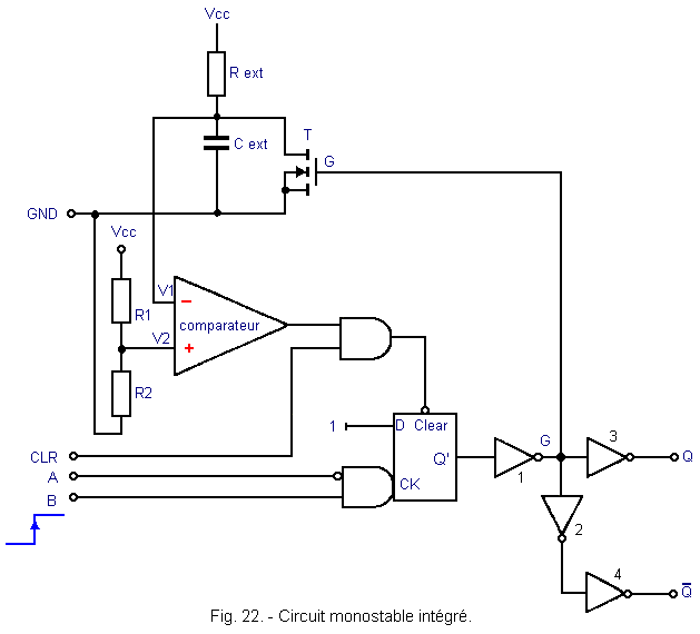
These are monostable circuits without particular conditions about the control signal. That is to say that it can indifferently be longer or shorter than the output pulse of the monostable. a) True monostable with a D flip-flop. The typical setup using a D flip-flop is shown in Figure 20-a, while Figure 20-b gives the truth table of the flip-flop. Figure 21 illustrates the operation of this arrangement. At rest, the monostable has its Q output at the low level (L). Indeed, if at power on the output Q is at the level H, the capacitor C loads and causes, a moment later, the activation of the CLEAR input of the flip-flop whose output immediately goes to the low level. The capacitor then discharges through the forward biased D diode. If a positive pulse on the input CK is applied at time t1, the high level applied to the input D is transferred to the output Q. This output being at the high level, the capacitor C is charged and the capacitor C is charged. phenomenon described above. The entry CLEAR becomes active at time t2, which returns Q to the low level. At time t3, the capacitor C is completely discharged. A new pulse can be applied to the CK input. With this assembly, a pulse, even very brief, triggers the rocker. This same control pulse can, moreover, be of a duration greater than that of output. This is therefore a true monostable, no particular condition being imposed on the duration of the input pulse. b) Monostable realized with a specific integrated circuit. The monostable circuit shown in Figure 22 uses a specific CMOS-type integrated circuit. This integrated circuit mainly comprises a D-type synchronous flip-flop and a comparator. A resistance REXT and a capacitor Cext are associated with this integrated circuit to define the time constant of this monostable. In the state of rest, the output Q' of the flip-flop is at the level L, so G is at the level H and Q, output of the monostable, at the level L. In this case, the transistor T leads and bypasses the capacitor Cext, imposing a zero voltage in V1, (input - of the comparator). The output of the comparator is therefore at level H. The CLEAR input of the flip-flop is at the level H, thus inactive. Figure 23 below shows you what happens when Control Input B changes from Level L to Level H.
The input A of the circuit which can be considered as a validation input is kept low. At time t1, the input B goes from the level L to the level H and thus the input CK of the flip-flop as well : the output Q' passes on the level H as well as Q. The voltage at the point G becomes zero and the transistor T is blocked. The capacitor Cext begins to charge through the resistor Rext. When the voltage at point V1 reaches the threshold of the comparator, it switches : its output goes to the L level, which activates the CLEAR input of the rocker. Q' then returns to the L level as well as the Q output of the monostable.
Simultaneously the transistor T leads and the comparator re-tilts at the level H to make the input CLEAR inactive. The monostable has returned to the state of previous stability.
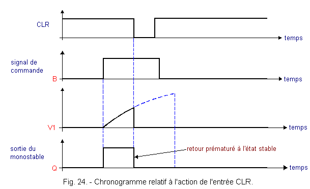
It should be noted that the CLEAR input of the D flip-flop can be activated at any time thanks to the CLR input of the circuit. There is therefore a way to interrupt the Q output pulse. This is illustrated in Figure 24.
It is also possible to trigger this monostable by a falling edge applied to the input A. In this case, the input B must be at the level H.
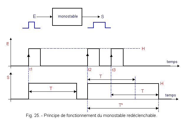
This is a last category we have not talked about so far. If we look again at Figure 23, we see that a new pulse 3 at the control input has no effect on the Q output of the monostable when it has just been triggered by the pulse 2 It will be said that it is a monostable non retriggerable. In contrast, there are monostable fixtures retriggerable, that is to say that a new control pulse occurring while the monostable is triggered is taken into account and extends the output pulse of a duration equivalent to that elapsed between the beginning of the first command and the beginning of the second. This is illustrated in Figure 25.
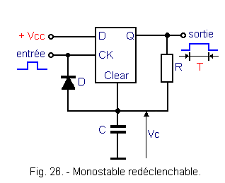
The total duration T' is the sum of T (time constant of the circuit) and "t3-t2". A sufficiently close sequence of pulses at the input E would permanently maintain the output S at level H. a) Realization with a rocker D.. The diagram has only one difference with that of Figure 20. In fact, in Figure 26, you see that the diode D is connected to the input and no longer to the output. This arrangement works with a particular condition for the control signal. The latter must have a duration greater than the time constant T of the monostable. Thus, it is a pseudo-monostable retriggerable.
Indeed, if the input CK is prematurely brought back to the level L, the diode D, directly biased, leads and the input CLEAR never reaches the level H since the capacitor C discharges immediately. The Q output would therefore remain permanently in state H.
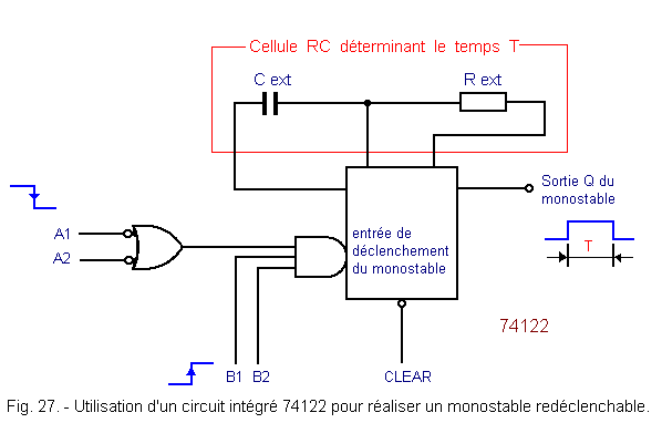
For the operation of the retriggerable monostable circuit, it is sufficient after a first control pulse to return the input to the level L and immediately bring it back to the level H before the period T has elapsed. Each time the input is brought back to the level L then to the level H, a new charge cycle of the capacitor starts again. b) Realization with an integrated circuit. The assembly shown in Figure 27 is a true retriggerable monostable that uses a specific integrated circuit of type 74122 or 74C122. In the idle state, the output Q is always at logic level L. To trigger this monostable, it is possible to use the four inputs A1, A2, B1 and B2.
It suffices to send a positive transition on either B1 or B2, provided that the other input (B1 or B2) is at level H and that at least one of the two inputs A1 or A2 is at level L.
If B1 and B2 are at the H level, it is also possible to trigger this monostable by a negative transition in A1 or A2. The two externally wired components Cext and Rext determine the duration of the output pulse T.
The active CLEAR input at L is a priority, ie it sets the Q output to L as soon as it is activated.
An exemplary application of retriggerable monostable is provided by fault detection systems in clock circuits.
Indeed, it suffices to choose a time constant of the monostable slightly greater than the clock period. It will be sufficient for a single clock face to be absent for the exit of the monostable to return to the state of rest and allow the reporting of an incident.
Envoyez un courrier électronique à Administrateur Web Société pour toute question ou remarque concernant ce site Web.
Version du site : 10. 4. 12 - Site optimisation 1280 x 1024 pixels - Faculté de Nanterre - Dernière modification : 02 Septembre 2016.
Ce site Web a été Créé le, 14 Mars 1999 et ayant Rénové, en Septembre 2016.
![]() 1.
3. 3. - MONOSTABLES
RELEASABLE
1.
3. 3. - MONOSTABLES
RELEASABLE
 Click here for the next lesson or in the summary provided for this purpose.
Top of page
 Previous Page
 Next Page
Nombre de pages vues, à partir de cette date : le 27 Décembre 2019
