Synchronous «D and JK» Flip Flops Available as Integrated Circuits :
5. - OVERVIEW OF SYNCHRONOUS ROCKETS AVAILABLE IN THE FORM OF INTEGRATED CIRCUITS
The scales «D and JK» of structure MASTER SLAVE that we examined are qualified in the catalogs of the constructors by the term "edge triggered", that is to say launches by front.
Synchronous flip-flops that switch on the positive edge of the clock signal are called «positive edge triggered», while those that switch on the negative edge are called negative edge triggered.
We will present you the most used synchronous flip-flops in practice, first those made in standard TTL or TTL-LS technology, then those realized in C.MOS technology.
5. 1. - SYNCHRONOUS FLIP-FLOP IN TTL TECHNOLOGY
5. 1. 1. - ROCKETS D
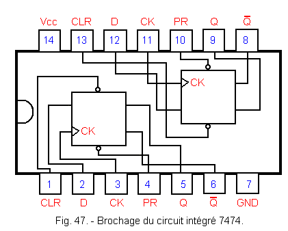
Figure 47 shows you the scheme and pinout of the integrated circuit 7474 which contains 2 independent "positive edge triggered" D flip-flops.
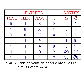
The truth table of each D flip-flop is given in Figure 48.
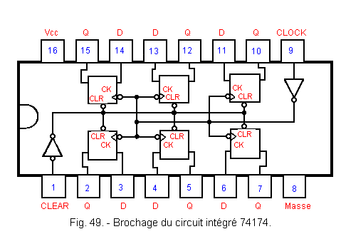
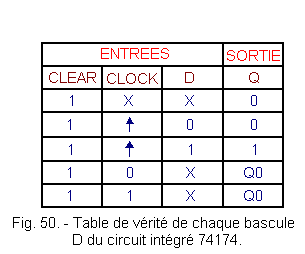
The integrated circuit 74174 contains, for its part, six flip-flops D «positive edge triggered». The CLOCK and CLEAR inputs are common to the six flip-flops. Each of the latches has only one output Q. The pinout of this circuit is shown in Figure 49.
The truth table of each flip-flop D of this circuit is given in Figure 50.
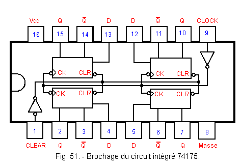
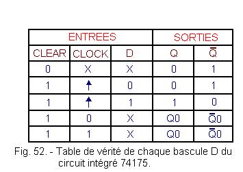
The integrated circuit 74175 contains four flip-flops D «positive edge triggered». The CLOCK and CLEAR inputs are common to the four flip-flops and each of them has two complementary outputs Q and ![]() .
.
The pinout of this circuit is shown in Figure 51.
The truth table of each flip-flop D of this circuit is shown in Figure 52.
![]() 5. 1. 2. - JK ROCKETS
5. 1. 2. - JK ROCKETS
The 74LS73 integrated circuit contains two JK «negative edge triggered» flip-flops with reset input. The pinout of this circuit is given in Figure 53.
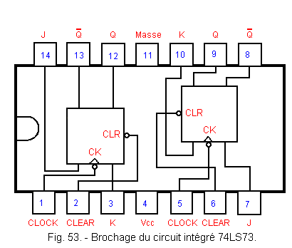
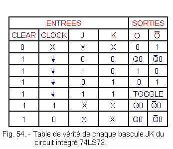
Figure 54 gives the truth table of each JK flip-flop of this circuit.
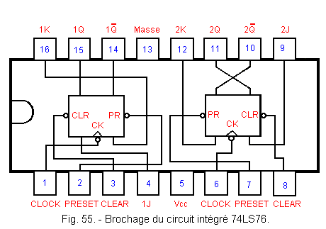
The 74LS76 integrated circuit contains two JK «negative edge triggered» flip-flops with reset and reset inputs. The pinout of this circuit is given in Figure 55.
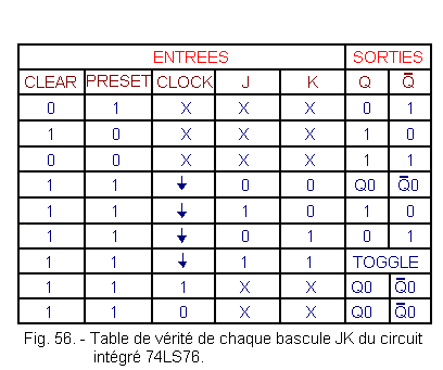
The truth table of each JK flip-flop is shown in Figure 56.
![]() 5. 2. - SYNCHRONOUS
MULTIVIBRATORS IN C.MOS TECHNOLOGY
5. 2. - SYNCHRONOUS
MULTIVIBRATORS IN C.MOS TECHNOLOGY
5. 2. 1. - ROCKETS D
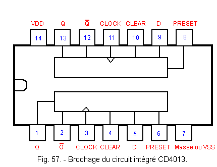
The integrated circuit CD4013 contains two «positive edge triggered» flip-flops D with reset and reset inputs 1. Its pinout is given in Figure 57.
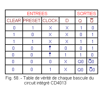
The truth table of each flip-flop in Figure 57 is shown in Figure 58.
![]() The integrated circuit CD 40174 is the C.MOS version of the integrated circuit TTL
74174. It is pin-compatible with this one and has the same truth table.
The integrated circuit CD 40174 is the C.MOS version of the integrated circuit TTL
74174. It is pin-compatible with this one and has the same truth table.
![]() It is the same for the integrated circuit CD 40175 which is the C.MOS version of the TTL 74175 integrated circuit.
It is the same for the integrated circuit CD 40175 which is the C.MOS version of the TTL 74175 integrated circuit.
5. 2. 2. - JK FLIP-FLOPS
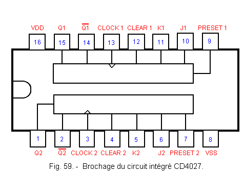
The integrated circuit CD 4027 is a double positive edge triggered JK flip-flop with reset and reset inputs. The pinout of this circuit is given in Figure 59.
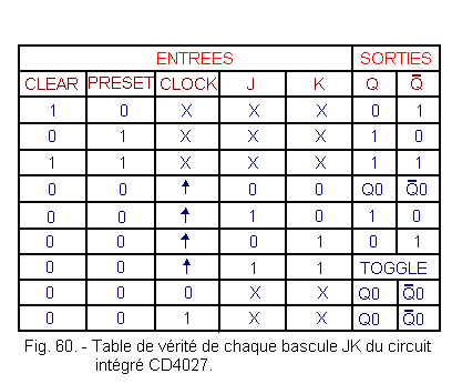
The truth table of each flip-flop of this circuit is given in Figure 60.
We are done with the review of synchronous flip-flops. In the next lesson, we will discuss the review of monostables, Schmitt Flip-Flops and astable multivibrators.
 Click here for the next lesson or in the summary provided for this purpose. Click here for the next lesson or in the summary provided for this purpose. |
|
 Previous Page Previous Page |
 Next Page Next Page |
Nombre de pages vues, à partir de cette date : le 27 Décembre 2019
Envoyez un courrier électronique à Administrateur Web Société pour toute question ou remarque concernant ce site Web.
Version du site : 10. 4. 12 - Site optimisation 1280 x 1024 pixels - Faculté de Nanterre - Dernière modification : 02 Septembre 2016.
Ce site Web a été Créé le, 14 Mars 1999 et ayant Rénové, en Septembre 2016.
 JK flip flops