Construction and Reading of the Cartesian Diagram :
CONSTRUCTION AND READING OF THE CARTESIAN DIAGRAM "1st PART"
In this lesson we will learn how to draw the graduated lines to be able to represent the given quantities in a suitable way.
In the most used representations in technique, the reference system consists of two perpendicular lines, one horizontal and the other vertical, called system axes, or more simply, axes.
The Figure 1 shows the two axes drawn separately so as to highlight the conventions that should be established for each of them.
Consider first the horizontal axis corresponding to the graduated line. We note that the axis of Figure 1-a, it has indeed two numbering : one that starts from the origin and goes to the right, and the other, which starts from the same origin and goes to the left ; in addition, the numbers to the left of the origin are all preceded by the sign "-" (minus). Each number, to the right or to the left of the origin, corresponds to one of the subdivisions and these subdivide at the same distance from each other.
The numbers and subdivisions on the right are called abscissa :positive abscissa on the right of the origin, and negative abscissa on the left.
Suppose that the horizontal axis represents the course of time as in the graph of Figure 1.
The origin 0 indicates the moment when we start counting. The positive abscissa 1 indicates that from the initial moment a unit of time has elapsed, namely a second, or an hour, or a day (this depends on the unit we have chosen).
The abscissa 2 indicates that from the initial moment two units of time have elapsed (2 seconds, 2 hours or 2 days). The abscissa 3 indicates three units of time after the initial moment, the abscissa 4 indicates four units of time after the initial time, and so on.
Negative X-coordinates also indicate units of time, but instead of representing the time that has elapsed from the initial moment chosen, they represent the time that preceded that initial moment. Thus, the negative abscissa - 1 indicates that there remains a unit of time to arrive at the initial moment, the abscissa - 3 indicates three units of time before the initial moment and so on towards ever more distant times before the initial moment.
Having in mind the meaning of numbers preceded by the sign - (- 4, - 3, - 2, - 1), we observe that by going to the right, that is to say, that in from a large number to a smaller one, the distance from the initial time decreases ; we can think that the arrow that indicates the increase of the times is not in agreement with the representation of the times to the left of the origin.
This deduction would be correct if we limit ourselves to looking at the numbering of the negative abscissae, without taking into consideration the progression of time. If we start counting the times, starting from a negative abscissa, for example - 4 seconds, and if we want to maintain this account in concordance with the real succession of seconds, we must express ourselves as follows :
minus four seconds, minus three seconds, minus two seconds, minus one second, time zero, one second (after zero time), two seconds, three seconds, four seconds ...
As we can see, the count that follows the flow of time always goes from left to right, in agreement with the arrow placed at the end of the axis, either that we count on the negative abscissae, or, all the more so because we count on the positive abscissae.
This point being cleared up, let us now consider the vertical axis traced on Figure 1-b.
We can repeat all the considerations made for the horizontal axis about origin, numbering and subdivisions. The only difference is in the name given to subdivisions and corresponding numbers which are called ordinates : positive ordinates above the origin and negative ordinates below that same origin.
The vertical axis must also represent a given physical quantity ; for example, it can represent the temperature and its respective values where the vertical axis is constituted by the scale of the thermometer. By comparing the vertical axis with the scale of the thermometer, we can easily guess the meaning of the arrow placed at the upper end of the axis: as in the example of the times for the horizontal axis, the arrow indicates the direction of increasing values.
In the particular case considered, it indicates in which direction the increases of the temperature occur.
An increase in temperature consists, from a negative order value, in going to the increasing values of the positive ordinates. This displacement goes from bottom to top, as indicated by the arrow, just as the mercury column of the thermometer rises when the temperature increases.
The meaning of the axes being established, let us now see how they are arranged on the sheet so as to form a reference system adapted to the establishment and reading of the graphs.
To use a reference system, it suffices to agree :
the position of each axis in the plane of the sheet,
how, starting from a point of the plane, to determine its abscissa and ordinate,
how, starting from the abscissa and the ordinate, locate a point in the plane.
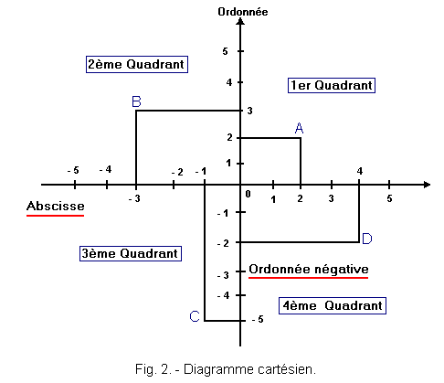
Among the possible solutions, in infinite number, adopt that of Figure 2, which, in many ways, is the simplest and most frequently used in electronics.
To compose this reference system, two axes must be crossed perpendicularly and so that their respective points of origin coincide. In addition, the following rule is set for passing points in the plane, to the corresponding values that can be read on the axes :
given a point, two lines passing through that point are considered ; one perpendicular to the axis of the abscissae and the other perpendicular to the axis of the ordinates.
The intersection of the line perpendicular to the axis of the abscissae with this axis indicates the value of the abscissae ; the intersection of the line perpendicular to the axis of the ordinates with this axis indicates the value of the ordinate.
Following the rule just stated, the abscissa and ordinate values of points A, B, C, D shown in Figure 2 can be easily established.
Point A: the perpendicular to the axis of the abscissa indicates on this axis the value 2 and the perpendicular to the axis of the ordinates indicates on this axis the value 2. Therefore, the point A corresponds to the value of the abscissa 2 and at the order value 2.
Point B: Following the same method as for point A, it is found that point B corresponds to the value of abscissa - 3 and the value of ordinate 3.
Point C :
it corresponds to the abscissa value - 1 and the ordinate value - 5.
Point D: it corresponds to the value of abscissa 4 and the value of ordinate - 2.
The graphs based on the previous rules are called Cartesian diagrams.
A Cartesian diagram divides the plane of the sheet into four parts, called quadrants,separated by two intersecting axes.
It is interesting to note that the points in the first quadrant (Figure 2), have positive abscissae and ordinates ; the points in the second quadrant have negative abscissae and positive ordinates ; the points in the third quadrant have abscissae and negative ordinates ; finally, the points in the fourth quadrant have negative ordinates and positive abscissae.
By judiciously combining the positive and negative abscissae with the positive and negative ordinates, each point in the plane can be represented by a pair of values (abscissa and ordinate) called coordinates of the point.
Usually, to denote a point in a graphical representation, we write the values of the coordinates in parentheses (after the capital letter constituting the point name) always putting first the value of the abscissa and in the second the value of the ordered.
For example, to designate the points in Figure 2, it is written in the abstract :
A (2 ; 2)
| B (-3 ; 3)
| C (-1 ; - 5)|
D (4 ; - 2)
You will always need to keep this shorthand in mind whenever a point on the chart will need to be designated by its coordinates, or conversely, when knowing the coordinates, a point should be placed in the plane.


 Footer
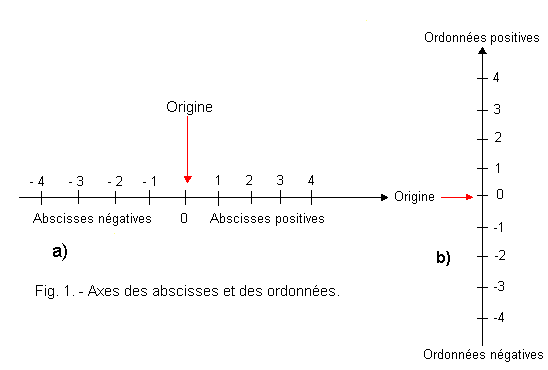
 Click here for the next lesson or in the summary provided for this purpose.
 Top of page
 Next Page